Connecting Kistler force plates
Kistler force plates must have both the analog channels and a control cable connected to the analog board. The following is a description of how to install a Kistler force plate with an analog board. It only describes the connection from the Kistler connection box to the analog board. For a description of the connection between the force plate and the connection box, please refer to the Kistler manual.
For information about digital Kistler integrations in QTM, see chapters Connecting Kistler digital force plates and Connecting Kistler DAQ Type 5695B.
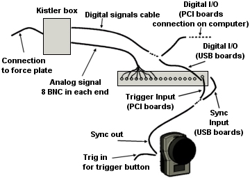
Start with the hardware connections to the analog board. The picture below is an example of the setup.
- Make sure that the force plate is working in Kistler's BioWare.
- Check whether you have a Kistler connection box 5606 or Kistler control unit 5233A2.
- Connect the analog signals (8 BNC cables) from the Kistler box
to 8 channels on the analog board.
- Make sure that the analog channels are connected in the correct order.
- Do not connect the analog signals from one force plate to different analog boards.
-
Connect the Digital cable from the Digital I/O on the analog board where the Kistler force plate is connected. The force plate is then controlled with the settings on the Force plate control settings page in the Project options dialog.
The connection differs between the analog boards. Check that you have the correct cable with Qualisys AB.-
USB-2533
There are two Digital I/O ports (DSUB15) on the front of the analog board. -
5606
Connect the DSUB15 end of the cable (230118) to port A on the analog board. Connect the DSUB37 end of the cable to the Digital input on the 5606 box, i.e. the bottom right connector. -
5233A2
You can either use a cable that controls two force plates per I/O port (230137) or a cable that controls one force plate on the first I/O port (230129).
Connect the DSUB15 end of the cable to port A on the analog board. Connect the DSUB37 end of the cable to the DSUB37 connector on the 5233A2 units.
Remember to press the Remote on the 5233A2 units to activate the digital control.If you want to use port B on the analog you must have a cable for 2 force plates in port A so that you can control the 3rd and 4th force plates from port B.
The Digital I/O is also used to reset the force plate before a measurement. It is important to not stand on a Kistler force plate when the reset signal is sent. It is sent at the following operations in QTM:
-
New file
-
Changing a setting in Project option in QTM during preview
-
Just before the Start capture dialog is opened before a capture
-
In a batch capture just before QTM starts Waiting for next measurement/trigger
The auto-zeroing of the force data can be disabled on the Kistler Force-Plate Control Settings page in the Project Options dialog, see chapter Force plate auto-zero.
-
- Remember to check that the sync out signal from the camera system is connected to the Sync input on the analog board, see chapter Connection of analog board. Otherwise the analog capture will not start.
This is all of the connections that is needed to connect the force plate to the analog board. Then you must add the force plate in QTM follow these steps:
-
Go to Analog board settings page in the Project options dialog. Make sure that it is the analog board where the analog channels and the digital I/O cable are connected.
-
Activate the channels for the force plate. You can rename the analog channels to the Kistler signal names so that it is easier to define the channels for the force plate.
-
Set the Sample rate for the analog board:
-
External Sync (recommended)
Select the correct synchronization output port and sample rate to get the desired frequency, see chapter Sample rate. -
Trigger start
Specify the frequency in multiples of the marker capture rate. For normal gait measurements you can use a sample rate of 600-1000 Hz. For sport measurements you need a bit higher sample rate.
-
-
Go to the Force plate control settings page and add the number of Kistler force plates that you want to control to the list.
-
-
Create the force plates on the Force data page in the Project options dialog.
-
Open the Force plate page.
-
Enter all of the calibration parameters for the force plates, see chapter Kistler force plate calibration parameters. They are found in the manual for the force plate. Use the option Select by forceplate control, so that the ranges used in the calculation are always correct.
-
Select the correct analog channels for each force-plate, see chapter Kistler force plate settings.
-
-
Enter the position of the force-plate, see chapter Force plate location. It is good to do this after each new calibration especially if the calibration L is not placed at the same position.
-
Activate the Calculate force data option on the Processing page. To see the force both in preview and in captured file make sure that it is activated both for Real-time actions and Capture actions.
-
Test the force plates in QTM. If there is no force, first check that there is no signal on the analog channels.
-
If there are signals on the analog channels the error is in the settings in QTM. Check the steps 1-5 above.
-
If there are no analog signals.
Disconnect the digital I/O cable from the Kistler unit and connect the cable for BioWare.
Start a measurement in BioWare and then start a measurement in QTM at the same time. The analog signals is sent to both BioWare and QTM, so you can see the force data in both.
-
If there is now analog signals in QTM the control signals are not sent from QTM to the Kistler force plate. Connect the digital I/O cable again. Check that it is connected to the correct ports and that the Remote button is pressed on the 5233A2 control unit.
It is possible to see the current ranges on the 5233A2 control unit and on some Kistler amplifiers. Check them so that the ranges are the same as in QTM.
-
If there is still no analog signal the BNC cables are probably connected to the wrong channels. Double-check the connections.
-
-