Connecting Kistler digital force plates
Hardware requirements
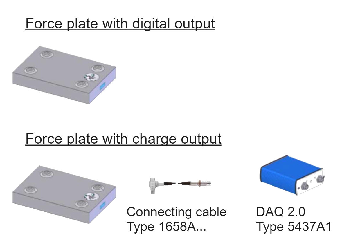
The Kistler force plate integration supports Kistler force plates with digital output of the following types:
-
Force plates with built in digital output (e.g., Digital force plate Type 9667AA...)
-
Force plate with charge output after upgrade (e.g., Type 9281EA/E or 9287CA/C with corresponding DAQ 2.0 Type 5437A1). For more information about upgrading force plates to digital force plates, contact Kistler support.
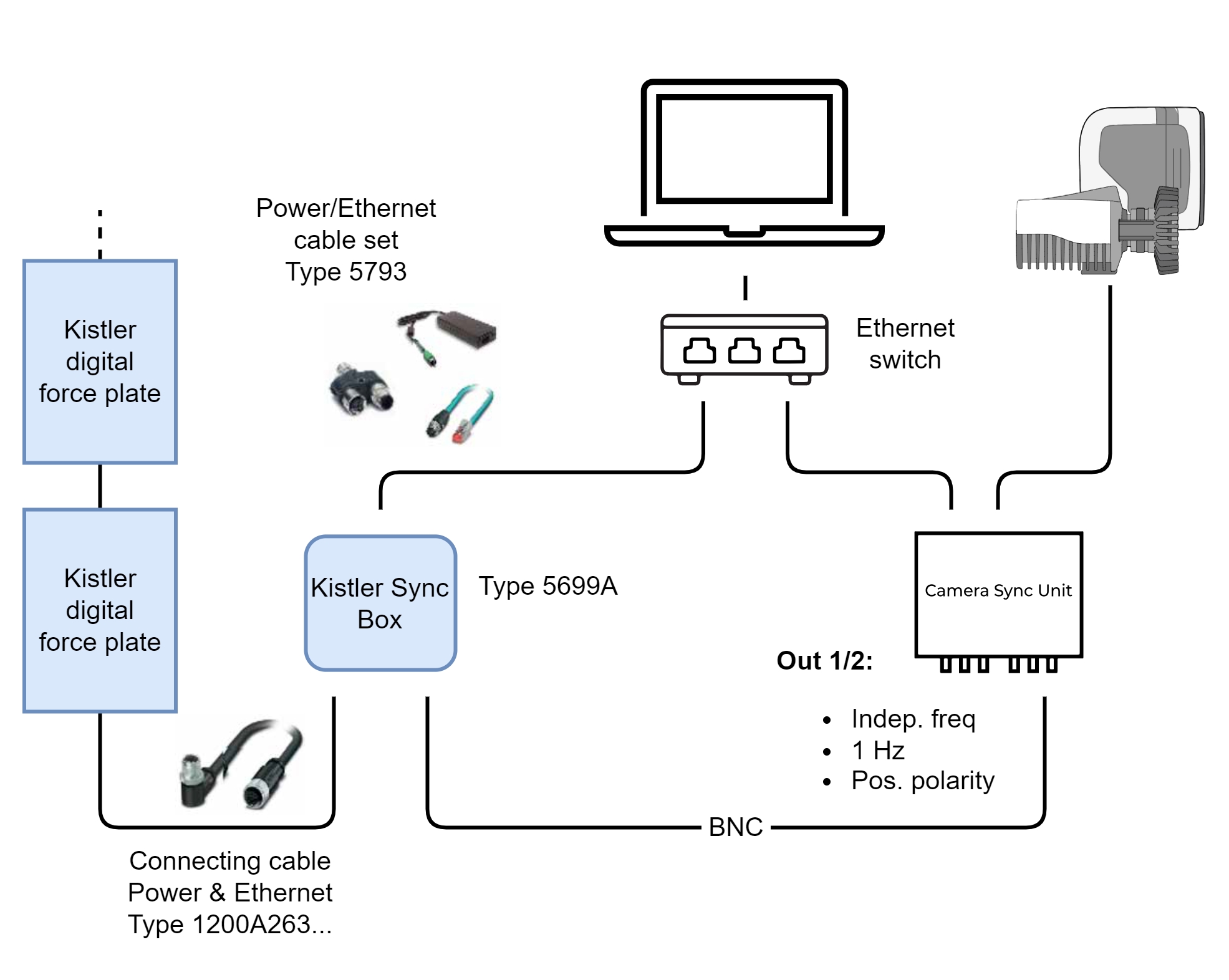
For the synchronization, you need a Kistler Sync Box Type 5699A and a Qualisys system with a Camera Sync Unit. If you have an Oqus system, you need a sync/trig splitter cable (art. 510870) connected to the control port of one of the cameras.
If you have force plates connected to a Kistler DAQ Type 5695B, please refer to chapter Connecting Kistler DAQ Type 5695B.
Software requirements
The following software is required for configuring and using Kistler digital force plates with QTM.
Kistler software:
-
BioWare (including DataServer)
-
SetupWizard.exe: Network setup wizard for Kistler devices
Please, refer to Kistler resources or support for information about version requirements and download.
Make sure that the latest version of the Kistler force plate integration for QTM is installed. Follow these steps to download and install the integration:
-
In QTM, open the Input Devices page under Project Options.
-
Click the Download device drivers link.
-
Download the installer for the Kistler force plate integration.
-
Run the installer.
Configuration of force plates
The Kistler system should be configured for use with QTM according to the instructions below. For more detailed information, contact Kistler or Qualisys support.
Network configuration
The force plates are connected to the computer through Ethernet. It is recommended to connect the Kistler system to the same network as the Qualisys cameras. Use the Kistler SetupWizard utility to configure the network settings of the Kistler devices (force plates and Kistler Sync Box). The Kistler devices should be configured with static IPv4 addresses.
If the static IP addresses of the Kistler devices are known, you can also configure the Qualisys camera network to use the same subnet as the Kistler devices, rather than reconfiguring the network settings of the Kistler devices. For instructions on how to configure the network adapter settings with QDS, see chapter Advanced.
To configure the network settings of the Kistler devices, follow these steps:
-
Take note of the subnet that is used for the camera network. In QTM, this can be found on the Camera System page under Project Options > Input Devices as the Interface in the Camera system settings information tab (typically, 192.168.254.x).
-
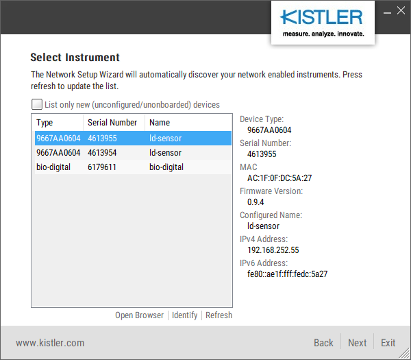
Run SetupWizard.exe and click Find devices. All Kistler devices connected to the network should show up in the list.

-
Select a force plate and click Next.
-
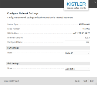
Set the IPv4 mode to Static IP. Optionally, change the configured name to help you identify the force plate. Click Next when done.
-
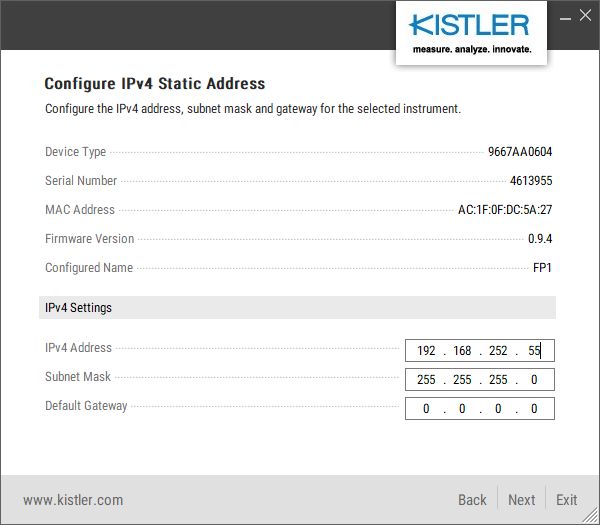
Enter a unique IP address for the device on the subnet noted in step 1. For example, if the subnet is 192.168.254.x, x can be set to any number between 2 and 255 (number 1 is reserved for the QTM computer).

-
Press Next to store the configuration changes to the device. The SetupWizard should show the confirmation page.
-
Press Start over to configure the next device, or Exit when all devices are correctly configured.

Once you set the IP addresses of the Kistler devices, you may need to reboot the Qualisys camera system to make sure that they don't have overlapping IP addresses.
Force plate configuration
Next, the force plate configuration should be defined in the Kistler BioWare software and stored in a configuration file. Follow these steps:
-
Open the Kistler BioWare program.
-
In the Setup menu, go to Hardware > A/D board and select Ethernet DAQ Device(s).
-
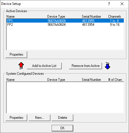
Open the Device Setup window (Setup > Hardware > Devices) and click New....
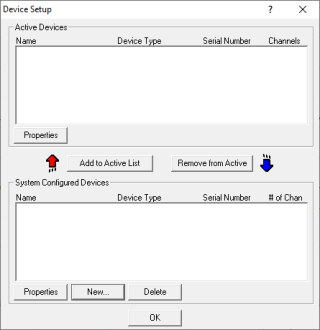
-
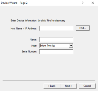
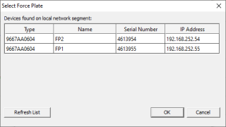
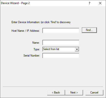
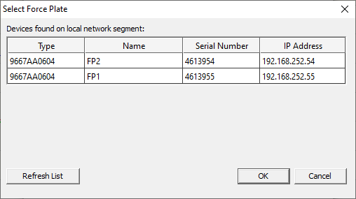
Click Find... to discover the connected Kistler force plates.
-
Select the first force plate from the list and click OK.
-
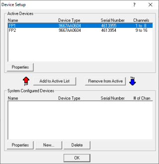
Add the force plate to the Active Devices list.
-
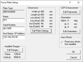
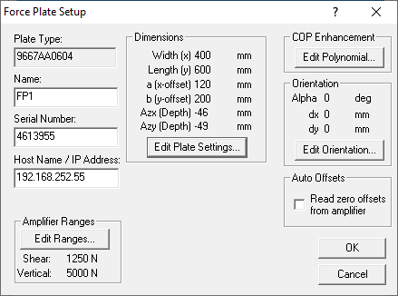
Optionally, you can edit the properties of the force plate, such as the amplifier ranges for shear and vertical forces. These properties will be stored in the configuration file.
-
Repeat steps 4-6 until all force plates are present in the Active Devices list.
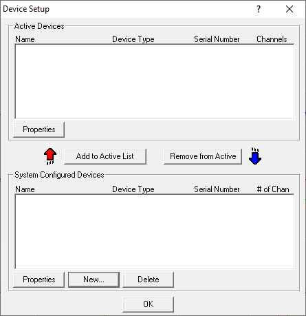
Once all devices have been added to the Active Devices list, you can create the configuration file. The order of the force plates in the configuration file, and consequently in the input device list in QTM is the same as that in the Active Devices list. Follow these steps to create the configuration file:
-
In the Setup menu, click Save DataSever configuration file....
-
Name the file config.xml and save it in the BioWare XML folder (typically C:\Kistler\BioWare\XML).
-
Open the config.xml file in a text editor and add the following lines after the <ConfigurationName> line to add the Kistler Sync Box (replace SerialNumber and Address with the actual serial number and IP address, respectively):
Copy<EthernetTriggerDevice>
<Type>bio-digital</Type>
<SerialNumber>1234567</SerialNumber>
<Manufacturer>Kistler</Manufacturer>
<Name>bio-digital</Name>
<Address>123.456.789.123</Address>
</EthernetTriggerDevice> -
Save the modified config.xml file.
Hardware setup
The Kistler system is connected as follows:
-
Connect up to 16 Kistler digital force plates to the Kistler Sync Box (Type 5699A). The digital Kistler devices can be connected in a daisy chain.
-
Use the Power/Ethernet cable set (Type 5793) to power the Kistler devices and to connect them to the computer via Ethernet. It is recommended to use the same network as used for the Qualisys camera system using an Ethernet switch.
Contact Qualisys support for a recommended Ethernet switch.
-
Connect the Out 1 or Out 2 port of the Qualisys Camera Sync Unit to the Sync input of the Kistler Sync Box with a BNC cable. If you are using an Oqus camera as sync device, use the Sync out connector of the Sync/Trigger splitter.
Set up and configuration in QTM
Add input device
Add the Kistler force plates to QTM:
-
In QTM, open the Input Devices page under Project Options.
-
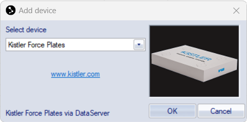
Click the Add Device button and select Kistler Force Plates in the drop down menu.

-
Check the Kistler Force Plates item in the Input Devices list. The Kistler Force Plates device should now show up as an input device under the Force Plates category. The force plates should be included in the device list as defined in the Kistler config.xml file.
-
Open the Kistler Force Plates settings page to access the Kistler device settings, see chapter Kistler Force Plates.
-
To change the frequency of the force data, set the Frequency value and press the Sync Settings button. Check that the frequency values for the force plate channels are updated.
It is highly recommended to use a sample frequency that is an integer multiple of the capture frequency.
Synchronization settings
To configure the synchronization, follow these steps:
-
In QTM, open the Synchronization page under Project Options > Input Devices > Camera System.
-
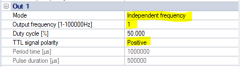
Use the following settings for the used Synchronization output (Out 1, Out 2 or Synchronization output):
-
Mode: Independent frequency
-
Output Frequency: 1 Hz
-
TTL signal polarity: Positive
-

Set up of force data
For setting up the force data in QTM, follow these steps:
-
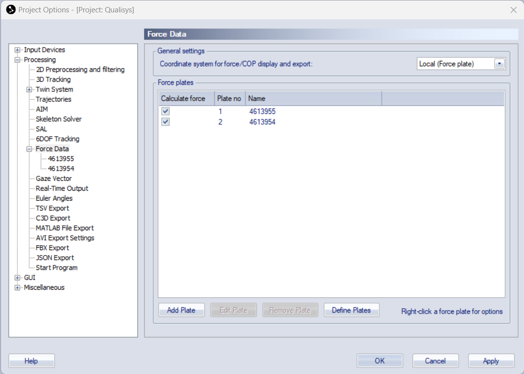
In QTM, open the Force Data page under Project Options > Processing.
-
Click the Define Plates button to add the Kistler force plates to the Force Plates list.

-
Make sure that the plates you want to use are enabled in the list.
-
Select a force plate and click the Edit Plate button (or double click) to edit the force data settings.
-
Make sure that the force plate dimensions are known in the Force plate status settings list. The force plate dimensions are retrieved automatically when connecting the force plates in QTM.
-
Set the location of the force plate with the Generate or View/Edit button, see chapter Force plate location.
-
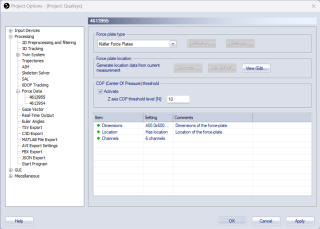
Optionally, activate the COP threshold to suppress the visualization of the force vector in QTM when there is no load on the force plate, see chapter COP (Center Of Pressure) threshold.
-
Activate the Calculate force data option on the Processing page. To see the force both in preview and in captured files, make sure that it is activated both for Real-time actions and Capture actions.

Capturing, viewing and exporting data
To collect data with the Kistler force plates, simply start a capture in QTM. The force data is automatically synchronized with the start of the capture. The force plates are automatically re-zeroed when starting a preview or a capture, so make sure that the force plates are unloaded at these instances.
To view the Kistler data during preview or a capture, open a Data Info window via the View menu (keyboard shortcut Ctrl + D), right-click in the window and select Analog data. The Kistler analog data includes forces and moments. To show the force data calculated by QTM, right-click on the Data Info window and select Force data.
When exporting to C3D, the analog data will be resampled to the closest integer multiple of the capture frequency, or higher depending on all analog data stored in the QTM file, see chapter C3D file format.