Force plate location
To be able to view the force vectors in the same coordinate system as the motion capture, the location of the force plate must be specified. The settings are the same for all force plate types and are done under the Force plate location heading on the Force plate page. The force plate location will be visualized as a purple square in the 3D view window.
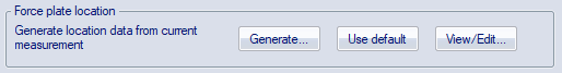
The three buttons have the following functions:
-
Generate
Automatically generate the force plate location from a capture of markers at the corners of the force plate, see chapter Generate force plate location from a capture.
-
Use default
Use default force plate location. This method is only available for the Gaitway-3D instrumented treadmill.
-
View/Edit
Manual review and possibility to edit force plate corner positions, see chapter Manual revision and specification of force plate location.
Generate force plate location from a capture
For automatic generation of the force plate location, place a marker on top of the four corners of the force plate. The markers do not need to be placed exactly on top of the corners, however, it is important that the markers are placed symmetrically for a correct estimation of the center of the force plate.
Follow these steps for automatic generation of the force plate location:
- Make a 1 second motion capture of these markers.
- Identify the markers, you can give them any label, and keep the capture file open.
-
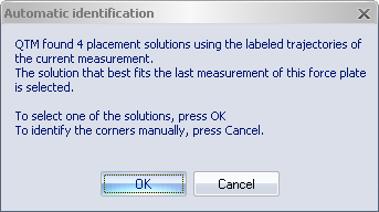
Open the Force plate page and click Generate. QTM tries to identify the corners of the force plate by comparing them to the width and length of the plate (as entered in the Force plate calibration parameters dialog). A dialog box like the one below is displayed:
-
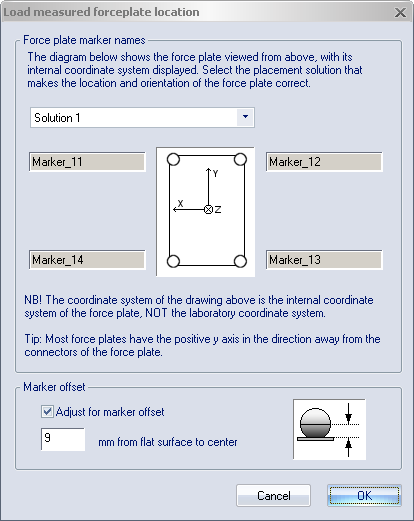
Click OK to open Load measured force plate location dialog, see below, and select one of the solutions found by QTM. Click Cancel to select the markers’ locations manually, see further down. Try to make sure that the orientation is correct. It is recommended to make a test measurement after the location process to see that the orientation is correct. If the force arrow is pointing downwards, you can use the Rotate 180 degrees option in the Force plate location dialog, shown below.
-
When spherical markers are used, the level of the force plate in the vertical direction will be the centers of the markers. If the level of the force plate should be exactly in level with the actual force plate, use the Adjust for marker offset setting in the Load measured forceplate location dialog. You can also click View/Edit in the Force plate settings dialog and adjust the vertical position.
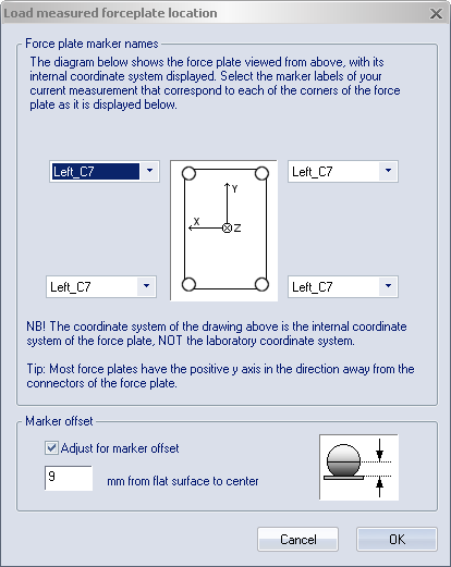
If QTM cannot find a solution among the labeled trajectories or if you click Cancel in the Automatic identification dialog, almost the same dialog will appear but you must select each corner manually, see below. in this case it is especially important to test that the force plate location is correct before making the measurements.
Manual revision and specification of force plate location
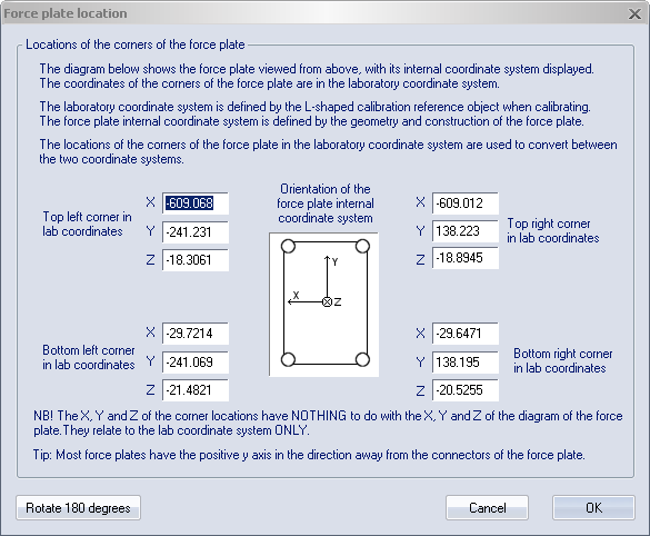
To manually specify the location click View/Edit. Enter the X, Y and Z coordinate (in mm) of the four corners of the force plate. The coordinates should be in the coordinate system of the motion capture (lab coordinates).
Make sure that the orientation is correct. Use the internal coordinate system of the force plate, shown in the dialog, to determine the orientation of the force plate corners. Most force plates have the positive y axis in the direction away from the connectors of the force plate.