Analog board settings
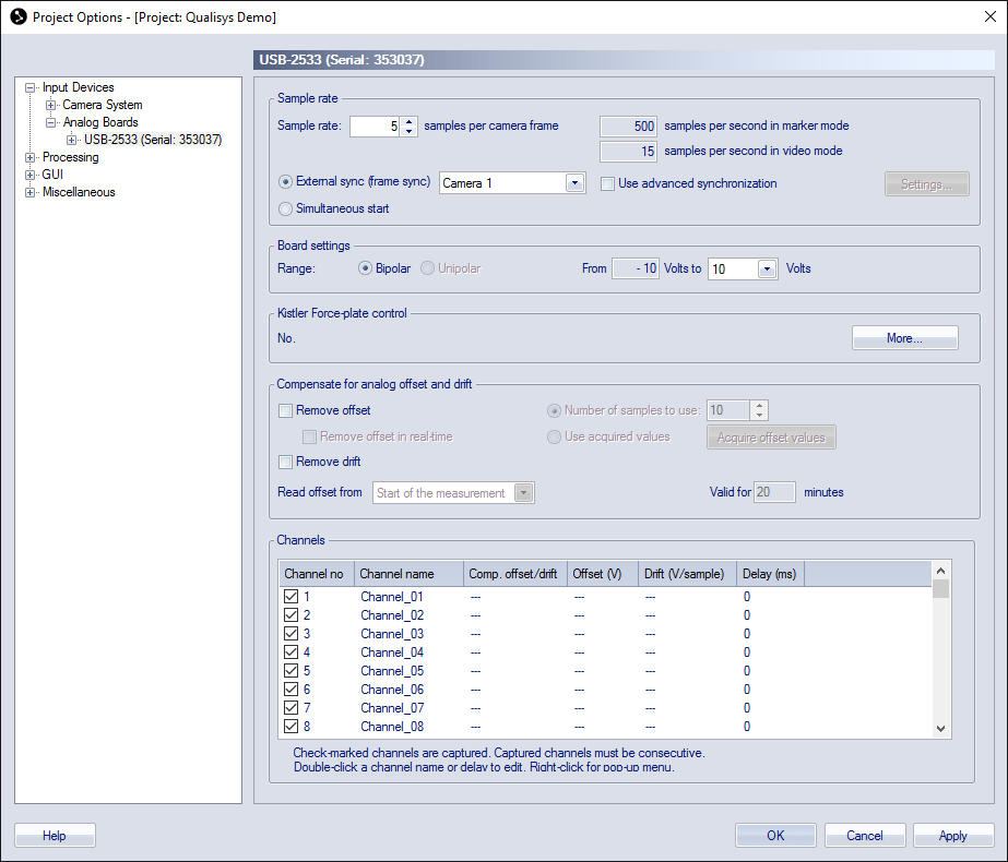
The page of each analog board contains the following settings.
Sample rate
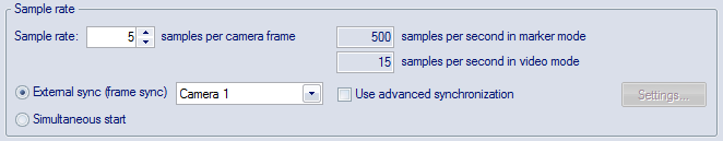
The Sample rate options control the frequency of the analog board. The sample rate is most often set in a multiple of the camera frequency, because it is easier to handle the data that way and this is for example a requirement for the C3D file. The default setting is one sample per camera frame, i.e. the same sample rate as for the camera system. What sample rate to use really depends on what you want to measure, for example for force data it is often enough with 500 to 1000 Hz.
The actual sample rate, in samples per second, for the analog board is shown in the text boxes to the right. When the External sync option is used with an Oqus camera as synchronization source, the sample rate is displayed both for marker mode and video mode . For all other options only the sample rate in marker mode is displayed.
The minimum analog sample rate is 20 Hz, which is a limitation set by the analog driver.
There are then two options for synchronizing the analog board to the camera system: External sync and Trigger start.
-
External sync (frame sync) with(default if available)
The analog board is frame synchronized so that the drift between the camera system and the analog data is eliminated. This is the recommended setting for a Qualisys system with a USB-2533 analog board. You can use any frequency for the analog board. For instructions on how to connect the sync out signal from an Oqus camera or a Camera Sync Unit to the analog board see chapter Setting up the analog board.
-
There are two options for the External Sync:
-
Camera selection
Select the camera where the Control port splitter is connected. The splitter can be connected to any camera in the system but you must specify which it is, because the sync out signal will be changed on the individual camera. The specified camera will automatically be set to a multiple of the capture rate and the Multiplier setting is automatically updated with the Sample rate option.
The frequency can be different on separate boards, but you then need to connect the boards to different cameras.
If the Reduced real-time frequency is used during preview, then the analog frequency during preview may differ from the ones reported on this page. The ratio between the camera frequency and the analog frequency set on the Synchronization page will however be the same, so you can calculate the analog frequency if necessary.
-
Use advanced synchronization
When the Use advanced synchronization option is activated the analog frequency is controlled directly from the Synchronization page. This means that the Sample rate option is disabled and you have to set the frequency directly. The advantage is that you can use the divisor and independent frequency modes so that you can in fact get any possible frequency.
-
Settings
To change the sync output frequency click on Settings to go directly to the Synchronization settings for the selected camera. There you can use any option for Synchronization output that you like, see chapter Synchronization output.
-
-
-
Simultaneous start
The analog board is just started on the first frame of the camera system, which means that there can be a small drift between the cameras and analog data.
The sample rate can be different on separate boards.
Board settings

Under the Board settings heading on the page for the analog board, there are settings for the range of the analog board.
Use the Range options to select Bipolar range (both negative and positive voltage) or Unipolar range (only positive voltage) and to select the voltage range that is used for the analog capture. The default settings are Bipolar and ± 10 Volts.
Force plate control

Under the Force plate control heading there is information about the setup of the control of the force plate. Click More to go to the Force plate control settings page.
Compensate for analog offset and drift
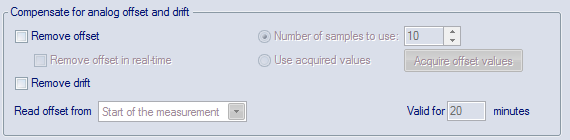
Under the Compensate for analog offset and drift heading there are settings for a filter which removes offset and drift. Activate the filter with the Remove offset and Remove drift options. The current compensation is displayed in the Channels list, see chapter Channels.
-
Remove offset
Removes an offset from the analog data. This setting can be used to remove the voltage level of a unloaded force plate. The offset compensation can either be calculated from the measurement or from an acquired list. The offset can be removed in RT/preview and in a file. When removed in a file the offset value cannot be changed only turned on and off, so it is important to set the correct settings before capturing the file. However if none of the options are selected you can still turn on the compensation in a file from the Data info window, the compensation will then be calculated from the start of the measurement.
-
Calculate offset from the measurement
Use the Remove offset from and Number of samples to use options to define the analog samples that are used to calculate the offset. Activate offset compensation in real-time with Remove offset in real-time.
-
Remove offset from
Set which part of the measurement to use when calculating the offset in the measurement. The default is Start of the measurement, but it can be changed to use the End of the measurementif there is noise at the beginning of the measurements.
For this offset setting it is important that the samples used in the file do not include any valid analog data. E.g. do not stand on the force plate at the start of the measurement since this data will be equal to 0 N if Remove offset is activated. In the case the calculated offset is higher than 5 V QTM will give you a warning, see chapter Analog offset warning. However you can always remove the offset compensation manually in the file from the Data info window, see chapter Analog data information.
-
Number of samples to use
The offset is defined as an average of the number of samples that are defined in the Number of samples to use option.
-
Remove offset in real-time
Activate the Remove offset in real-time option to remove the analog offset during RT/preview as well. Only activate this if you are using the RT data. The offset will always be calculated from the beginning of the preview so it is important that this analog data is correct. For example if you zero a force plate amplifier after you started the RT/preview then the data will be wrong, because then the offset was calculated on the signal from the unzeroed amplifier. The data will however be OK when you capture the file, because then QTM calculates a new offset in from the file.
-
-
Acquire list of offset values
The Use values in list below option can be used if you have a static offset that you can acquire during the real-time.
-
Use values in list below
The offset is saved before the measurement and displayed in the Channels list below. This option is not available in combination with Remove drift.
Acquire the offset during RT/preview with the Read current values button. Make sure that the analog signal is correct when you press Start in the Acquire offsets dialog. Because the offset is then stored the analog signal can include valid data in the beginning of RT/preview and in a file. E.g. you can stand on the force plate when the measurement starts.
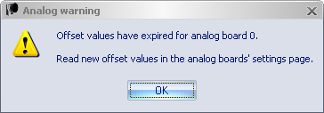
The offset is valid for the number of minutes specified next to the option. How long time you can use depends on the drift of the analog signal. The analog warning below is displayed when you start a measurement and the time has expired.
-
-
-
Remove drift
Calculates a slope from the first and the last samples of the measurement. The number of samples used to calculate how much to remove from the analog data is defined in the Number of sample to use option. This slope is then deleted from the analog data. This setting can be used to remove an output drift of a force plate that slowly changes the voltage level during the measurement.
The drift compensation is only applied on a file and cannot be used with the options Read offset from end of measurement and Use values in list below. Because those implicates that the analog data is not correct at the beginning of the measurement.
When the drift filter is activated it is important that the samples in the beginning and end of a in file do not include any valid analog data. E.g. do not stand on the force plate at the start and end of the measurement since this data is used to calculate the drift. However you can always remove the drift compensation manually in the file from the Data info window, see chapter Analog data information.
Channels
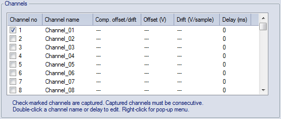
The channels of the analog boards are listed under the Channels heading.
To use a channel select the corresponding check box in the Channel no column. The selected analog channels must be in successive order. For example, if only channel no 3 and channel no 7 are used all channels in between must also be selected. Double-click on the Channel name column to rename the channel.
An individual delay in ms can be compensated for on each analog channel, for example it can be used with Delsys Trigno EMG that has a known delay of 48 ms. Double click on the Delay (ms) column to edit the delay of that channel. The delay is specified in ms, but the actual delay will be in the closest number of analog samples to that time. The compensation means that the analog samples on the channel is translated to match when it actually happened, for example with a 48 ms delay a signal that comes at 1.000 s will be translated to 0.952 s.
The delay is not applied in real-time processing.
To edit the other settings right-click for the menu below.
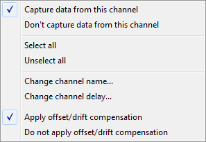
The menu contains the following options.
-
Capture data from this channel
Use this channel, the same as selecting the checkbox.
This option applies to all selected channels, i.e. the line is colored blue.
-
Don't capture data from this channel
Do not use this channel, the same as deselecting the checkbox.
This option applies to all selected channels, i.e. that line is colored blue.
-
Select all
Use all of the channels
-
Unselect all
Use none of the channels. Sometimes the fastest way to select a new range of channels.
-
Change channel name...
Open a dialog to change the channel name.
-
Change channel delay...
Open a dialog to change the channel delay.
-
Apply offset/drift compensation
Use this options to apply offset and/or drift compensation. However you can always turn off the compensation in a file from the Data info window.
This option applies to all selected channels, i.e. that line is colored blue.
-
Do not apply offset/drift compensation
Use this option to not apply the offset and/or drift compensation. However you can always turn on the compensation in a file from the Data info window.
This option applies to all selected channels, i.e. that line is colored blue.
The current settings under the Compensate for analog offset and drift heading is displayed in the last three columns. The different settings are described below.
-

If no compensation is activated all three columns display ---. This means that no compensations is applied in RT/preview or in a file. However you can turn on the compensation in a file from the Data info window. The compensation will be calculated from the Use the first and last option.
-

If the compensation is activated with the option Use the first and last, then the Offset and Drift columns says Calculated. The offset compensation will be applied in both RT/preview and in a file and calculated from the first samples, which means that it is important that there is no signal on the analog channel and the start of RT/preview or in the beginning of a file.
The drift compensation is however just applied in the file, since it isn't calculated for the RT/preview. For the drift compensation it is important that there is no analog signal in the beginning and the end of the file.
-

If the compensation is activated with the option Use values in list below, then the last read value is displayed in the Offset column. The offset compensation will be applied in both RT/preview and in a file. However since the offset values have already been stored there can be an analog signal in the beginning of RT/preview and a file. Start RT/preview and use the Read current values button to updated to offset values for the channels where the compensation is activated.
The Drift column displays ---, because the drift cannot be compensated for in this mode.
-

When the compensation of a channel is deactivated by the Do not apply offset/drift compensation option, then the Comp. offset/drift column displays No. The compensation is then not applied, but it can be activated in a file from the Data info window.
-