Synchronization output
The Camera Sync Unit (CSU) has three synchronization outputs, Out 1, Out 2 and Measurement time. The outputs Out 1 and Out 2 can be configured controlled to get a customized synchronization output.
For Oqus systems, each camera has a synchronization output, which can be accessed via a splitter cable connected to the control port. The Synchronization output can be controlled to get a customized synchronization output from the cameras. Additional modes for the Synchronization output for Oqus cameras are Camera frequency – Shutter out, Measurement time and Wired synchronization of active markers. The settings apply to individual cameras so that there can be different synchronization outputs within the same system. Select the cameras in the device list to the left. The synchronization signal is sent as soon as the camera is measuring, i.e. both during preview and capture, with the exception of measurement time, which is only sent during capture, and 100 Hz continuous, which is always sent. For a description of how to use the sync output see chapter Using Sync out for synchronization.
When a Camera Sync Unit is included in the system, QTM only displays the Synchronization settings of the Camera Sync Unit. The synchronization settings of Oqus cameras are not displayed.
If you want to use a sync output signal that is faster than 5000 Hz with an Oqus system, you must use the master camera as sync device. The master camera is displayed with an M next to the ID in the camera list to the left.
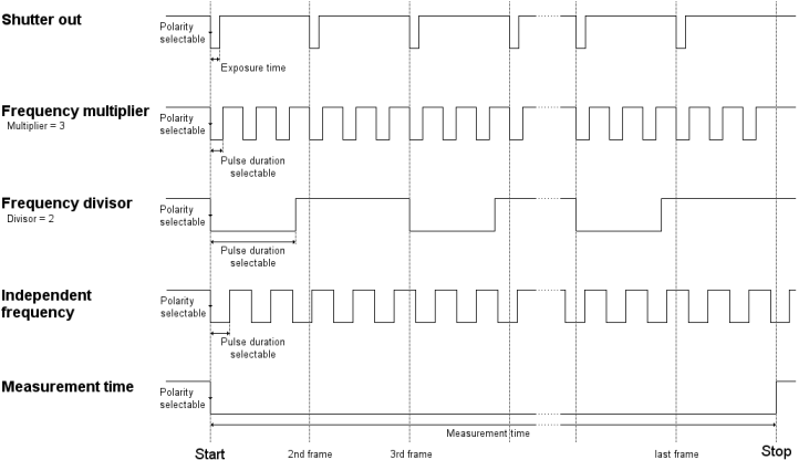
There are four different sync modes which are described below. The image below is a description of the different sync output settings.
The following modes are available. The settings depend on the chosen mode.
Camera frequency - Shutter out (Oqus)
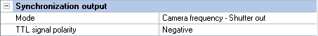
This is the default setting for the Oqus cameras. In this mode a pulse is sent for each frame captured by the camera and the pulse has the same length as the exposure time.
Set the TTL signal polarity to change the polarity of the signal. Negative means that the sync out signal will be high until the first frame when it will go low.
Frequency multiplier/Frequency divisor
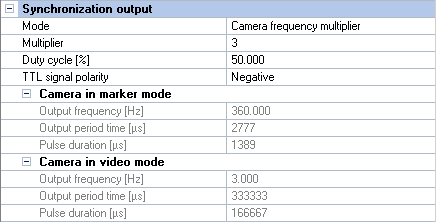
Use this mode to set the frequency as a multiplier/divisor of the camera capture frequency. The multiplication factor/divisor is controlled with the Multiplier/Divisor setting. The current Sync output properties (Frequency [Hz], Period time [µs] and Pulse duration [µs]) are shown below the setting both for marker mode and video mode (if applicable), because the marker and video capture rates can be different. The Sync output frequency will change if any of the capture rates are changed. The displayed period time is rounded to the nearest microsecond, but the number of pulses will always be correct compared to the camera frequency.
The maximum Multiplier is 1000 and the maximum Output frequency is 100000 Hz.
The video capture rate is individual per camera, which is indicated by a red number if it differs. Select only the camera that Sync out is connected to find out the frequency in video mode.
The Duty cycle setting for controls how long the pulse will be in percent of the current Period time. The actual Pulse duration is displayed for the marker mode and (if applicable) video mode, respectively.
The pulse starts at the start of each period, i.e. you cannot apply an offset to the pulse. However, by changing the Duty cycle and the TTL signal polarity you can get an edge at any time between two frames.
Set the TTL signal polarity to change the polarity of the signal. Negative means that the sync out signal is high until the start of the first frame when it will go low. Each signal will then be synchronized with its corresponding capture frame which depends on the Multiplier/Divisor setting, see image above.
Independent frequency
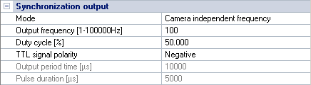
Use this mode to set the frequency independently of the camera capture frequency. The Output frequency can be set between 1 and 100000 Hz. When changing the frequency the Period time [µs] will then update to its corresponding value.
The Duty cycle setting for controls how long the pulse will be in percent of the
current Period time. The actual
Pulse duration (in μs) is displayed below.
Set the TTL signal polarity to change the polarity of the signal. Negative means that the sync out signal is high until the start of the first frame when it will go low. The first pulse will always be synchronized with the camera capture. The following pulses will be dependent on the relation between the camera capture rate and the Output frequency.
Measurement time (Oqus)
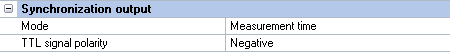
Use this mode to get a pulse that lasts for the whole capture time. The output will go low/high at the start of a capture and not go high/low until the end of the last frame. Measurement time applies only to captures, not to preview.
Set the TTL signal polarity to change the polarity of the signal. Negative means that the sync out signal is high until the start of the first frame when it will go low.
For the Camera Sync Unit, measurement time is not available as a mode for the Out 1 and Out 2 ports. Instead, the it has a separate Measurement time output with the same options.
100 Hz continuous
Use this mode to output a continuous 100 Hz TTL signal. It is sent even when the system is not measuring so that external equipment can lock on to this signal. In Oqus systems, only one camera can have this option activated.
Notes on 100 Hz continuous mode:
-
When External timebase is activated it is automatically changed to the Internal 100 Hz option. In this scenario, the device which is set to 100 Hz continuous output will be used as a timebase.
-
This option is required for the Twin system frame synchronization option, in which case it is selected automatically.
-
The 100 Hz continuous output is not available on Oqus 1, 3 and 5 series cameras.
System live time
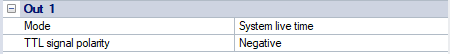
Use this mode to get a pulse that lasts for the whole preview or capture time. The output will go low/high at the start of a measurement and not go high/low until the end of the last frame. System live time applies to both preview and captures.
Set the TTL signal polarity to change the polarity of the signal. Negative means that the sync out signal is high until the start of the first frame when it will go low.
Wired synchronization of active markers (Oqus)
Use this mode to synchronize the active markers via a wire connected from Sync out on the camera to the Sync in connector on the driver. The signal is pulsed so it cannot be used for any other synchronization.
This mode is only available if you are using active markers.
Controlled by Analog board
The camera synchronization output is controlled by the settings for an analog board, see chapter Sample rate.