Kistler calibration and settings
The following settings apply to Kistler analog force plates, and the legacy Kistler DAQ Type 5698A/B integration (deprecated in QTM 2024.1).
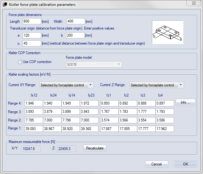
Kistler force plate calibration parameters
For information on how to connect a Kistler force plate see chapter Connecting Kistler force plates.
Select the Kistler force plate type and click Calibration under the Force plate type heading to go to the Kistler force plate calibration parameters dialog.
Force plate dimensions
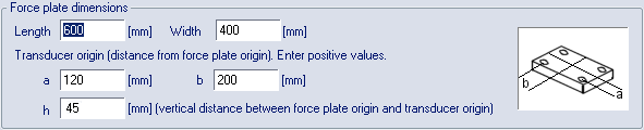
Under the Force plate dimensions heading you should enter the length, width and transducer origin parameters for the Kistler force plate. These parameters can be found in the documentation that is delivered with the Kistler force plate. If you cannot find these values, please refer to Kistler support.
Enter the absolute values of the parameters, that is for the h value write 45 when the Kistler manual says -45.
Kistler COP Correction
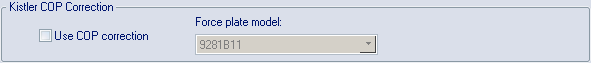
The COP correction is a method developed by Kistler to improve the accuracy of the COP calculation. According to Kistler the error can be reduced by 3-5 times. The method is implemented in QTM from the paper "Improving COP Accuracy with Kistler Force Plates", contact Kistler for more details.
Activate the Kistler COP correction with the Use COP correction checkbox. Select the force plate model from the Force plate model list, the method is only available for the force plates in the list.
The coefficients are force plate model (type number) specific. If in doubt, please contact Kistler.
The coefficients apply only if the force plate is mounted on a rigid foundation according to Kistler specifications.
Kistler scaling factors
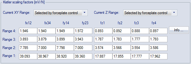
The scaling factors of the Kistler plate must be entered under the Kistler scaling factors heading. The scaling factor ensures that the force data is scaled correctly. Follow these steps to use the correct scaling factors.
If you update from a version earlier than QTM 2.7 all of the ranges will get the value of the currently entered range. Enter the correct values for all of them so that you can switch ranges more easily.
-
How to find the scaling factors differs between internal and external amplifiers.
-
Internal amplifier
For a Kistler force plate with internal amplifier enter all of the scaling factors that are found in the calibration certificate matrix of each force plate.
-
External amplifier
For a Kistler force plate with external amplifier you must calculate the scaling factors, see instructions below.
-
-
Then select the range with the Current XY range and Current Z range options:
-
Selected by forceplate control
The default option is Selected by forceplate control, which means that the range is controlled by the ranges set on the Force plate control settings page.
The force plates will be ordered by the analog channels that they are connected to, so that the one with the first channels will use the ranges of the first plate on the Force plate control settings page.
-
Range 4 - Range 1
You can select the range manually if you don't use the analog board to control the force plate ranges. Range 4 will give you the maximum force range and range 1 will give you highest sensitivity, i.e. minimum force range. It is important to use the same range as is used by the force plate to get correct forces, you can use different ranges for the XY and Z settings.
-
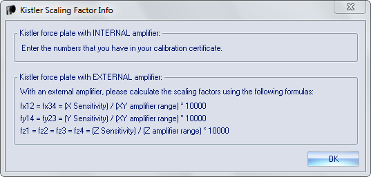
Calculating scaling factors with external amplifier
For a Kistler force plate with external amplifier, the scaling factors need to be calculated from the data found in the calibration certificate matrix of each force plate, click on Info for more information. Calculate the scaling factors for all of the ranges with the help of the formulas in the Kistler scaling factor info dialog. The force plate sensitivity parameters and the value of the ranges are found in the Kistler calibration sheet.
Maximum measurable force

Under the Maximum measurable force heading the maximum measurable forces, for the specific settings, are shown in N for the X/Y and Z directions. Click Recalculate to recalculate the maximum forces when a setting has been changed.
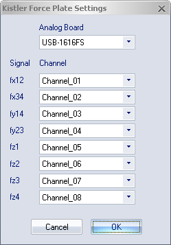
Kistler force plate settings
Select the Kistler force plate type and click Settings under the Force plate type heading on the Force plate page to open the Kistler force plate settings dialog.
-
First you must select the analog board where the force plate is connected from the Analog board drop-down list.
-
Then associate each signal from the force plate with its respective analog channel with the Channel settings.
On the Analog board (...) page the channel names can be renamed to match the signal names.
For more information about these settings see the manual of the Kistler force plate.