6DOF tracking
![]()
The 6DOF Tracking page contains the 6DOF Tracker parameters and the list of Rigid bodies. The 6DOF tracker uses this information to calculate the position and rotation from the 3D data, see chapter 6DOF tracking of rigid bodies.
It is also possible to export the 6DOF tracking output to another computer and as an analog signal, see chapters Real-Time output and 6DOF analog export, respectively.
6DOF Tracker parameters
![]()
Specify the global tracker parameter for the 6DOF tracking under the 6DOF Tracker parameters heading. More 6DOF tracker parameters, in particular Min. markers, Max. residual and Bone tolerance, are available for the individual rigid body definitions, see chapter Rigid bodies.
-
Reidentify all body markers
Enable this option to reidentify the markers for all rigid bodies using the Rigid bodied definitions and settings for reprocessing. Only available when reprocessing a file, for more information see chapter Calculating 6DOF data.
Rigid bodies that are parts of AIM models are not affected by this option.
-
Do not require that the whole body is visible before identifying it the first time
Enable this option to remove the requirement that all markers of the rigid body must be visible to identify the body the first time. This can help the 6DOF tracker to find a solution in case only a part of the body is visible.
-
Calculate missing markers in rigid bodies
Active the option to calculate virtual trajectories for lost 6DOF markers in RT and files, for more information see chapter Virtual markers calculated from 6DOF data.
For information on 6DOF tracking see chapter 6DOF tracking of rigid bodies.
Rigid bodies
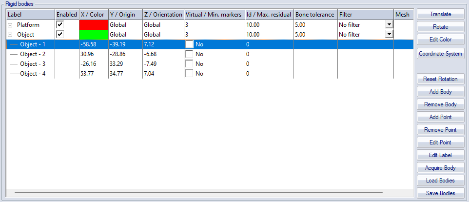
The Rigid bodies list contains the definition of the 6DOF bodies. The bodies are used by the 6DOF tracking to find the measured rigid bodies in a motion capture. The list consists of the following columns. In case a column refers to separate items for the rigid body definition or its points, respectively, this is indicated by the / separator.
Rigid bodies:
-
Label
The Label column contains the name of the rigid body and its points. Double-click on the name of the rigid body or the points to edit them. The points can have any name, however if the same name is used in another 6DOF body or an AIM model then you need to follow the instructions in chapter How to use 6DOF bodies in an AIM model.
-
Enabled
Enable or disable calculation of 6DOF data for rigid bodies with the check box in the Enabled column. Disabled rigid bodies will appear as "Disabled" in the Data Info window and count for the indexing of rigid bodies in the real-time stream.
-
Color
The color of the rigid body is displayed in the X / Color column on the same row as the name of the rigid body. Double-click on the color to open the Color dialog where any color can be selected. The color is used in the 3D view window for the markers of the rigid body and for its name.
The 3D trajectories automatically have a slightly brighter color than the 6DOF body and therefore it will look like the markers have two colors.
-
Origin, Orientation
The coordinate system that the 6DOF body data refer to is displayed in the Y / Origin and Z / Orientationcolumns on the same row as the name of the rigid body. Double-click on either the origin or the orientation setting to open the Coordinate system for rigid body data dialog, see chapter Coordinate system for rigid body data.
-
Min. markers
Specify the minimum number of markers required for 6DOF tracking of the rigid body.
-
Max. residual
Specify the maximum residual accepted for 6DOF tracking of the rigid body.
-
Bone tolerance
The Bone tolerance (in mm) is the maximum separation between the lengths of the corresponding bones in a rigid body definition and a measured rigid body. E.g. if the Bone tolerance is specified to 5.0 mm and the current bone in the rigid body definition is 100.0 mm, then the measured separation between two markers must be in the range of 95.0 - 105.0 mm for the tracker to accept the possibility that the calculated markers may be the pair specified for the rigid body.
-
The default value of the Bone tolerance is 5 mm. Increase the value of the parameter if the 6DOF tracking cannot find the body. Decrease the value of the parameter if a body is found but the orientation or something else is wrong.
-
The effect of the Bone tolerance differs slightly between RT and in files. In RT the marker that is outside the tolerance will be unidentified and the 6DOF body will be calculated from the remaining markers. In a file the automatic 6DOF tracker will discard the whole trajectory that is wrong and then calculate the 6DOF body from the other trajectories. However if you identify the trajectories manually and then just Calculate 6DOF, then there will be no 6DOF data in frames where a marker is outside the tolerance.
-
Filter
Select the filter for smoothing 6DOF data. The default is No filter. The filter is applied both in real time and in a capture. For more information about smoothing 6DOF data, see chapter Smoothing 6DOF data.
-
Mesh
Object file of 3D mesh associated with rigid body. Double-click on the mesh setting of the rigid body to open the Mesh Settings dialog, see chapter Rigid body Mesh Settings dialog.
Points:
-
X, Y, Z
The X, Y and Z columns contain the coordinates of the points in reference to the local origin. Double-click on the coordinates of to edit them.
-
Virtual
Select this option to make a point in the 6DOF body virtual, see chapter Virtual markers calculated from 6DOF data.
-
Id
The ID of the trajectory in case the point is associated with a sequentially coded active marker.
The options that are used to edit the rigid bodies or their points are described below:
-
Translate
With Translate the local origin of the 6DOF body definition can be moved to any place in reference to the points of the body, which means that the rotation center of the body is changed. The local origin is also the origin of the coordinate system that represents the 6DOF body in the 3D view. Click Translate to open the Translate body dialog, see chapter Translate body.
-
Rotate
With Rotate the pitch, roll and yaw of the local coordinate system is changed. This will change the orientation of the local coordinate system in reference to the global coordinate system. I.e. it changes the rotation of the rigid body where its roll, pitch and yaw are zero in reference to the global coordinate system. Click Rotate to open the Rotate body dialog, see chapter Rotate body.
-
Edit color
Open the Color dialog where any color can be selected. The color is used in the 3D view window for the markers of the rigid body and for its name.
The 3D trajectories automatically have a slightly brighter color than the 6DOF body and therefore it will look like the markers have two colors.
-
Coordinate system
Change the definition of the local coordinate system, see chapter Coordinate system for rigid body data.
-
Reset rotation
This will reset the orientation of all the rigid bodies in the list. Reset means that the local coordinate systems will be aligned to the global coordinate system and all the angles will therefore be zeroed.
The angles may differ from zero after reset if another reference system than the global coordinate system is defined in the Coordinate system for rigid body data dialog.
-
Add body
Add a new body to the Rigid bodies list. The new body will be empty and called ’New Body #1’, ’New Body #2’ and so on.
-
Remove body
Remove the selected body from the Rigid bodies list.
-
Add point
Add a point to the selected rigid body.
-
Remove point
Remove the selected point.
-
Edit point
Edit the selected point. Use Tab and Shift+Tab to go to the next respectively the previous coordinate.
-
Edit label
Edit the selected label (rigid body or point).
-
Acquire body
Acquire the rigid body definition from the current marker positions in RT/preview mode, see chapter Acquire body.
-
Load bodies
Loads bodies to the Rigid bodies list from an XML file.
Load bodies will overwrite any other bodies in the list.
-
Save bodies
Save the bodies and all of the individual options in the Rigid bodies list to an XML file. Specify the name and the folder and click Save. The file can be edited in a text editor, e.g. Notepad. The xml format is the same as used for the RT protocol, see 6DOF xml parameters.
Make sure that all of the bodies for the measurement are in the same file, since Load bodies overwrites the bodies in the list. If you want to combine the rigid bodies from two or more different files you can copy-past them into a single file.