Rotate body
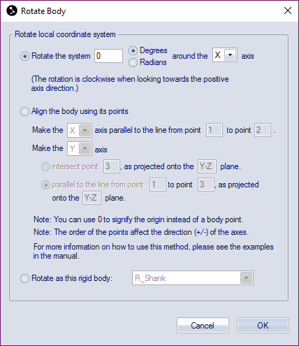
The Rotate body dialog contains the following ways to rotate the local coordinate system:
-
Rotate the system
Rotate the local coordinate system clockwise around one of the axes, when looking in the positive direction. Choose the angle of rotation either in Degrees or in Radians. Then select which axle to rotate round, X, Y and Z.
The rotation are not changed by the Euler angles but will always be the same.
-
Align the body using its points
Define the rotation of the local coordinate system with three or four points from the rigid body definition. You can use 0 to signify the origin of the local coordinate system if you want to use it as one of the points. See detailed instructions for using this method below.
-
Rotate as this rigid body
Rotate the local coordinate system to current orientation of the selected rigid body in the list. This will zero the orientation of the body in the list if its orientation is referred to the current rigid body.
Follow these steps to set the rotation with the "Align the body using its points" method:
-
First start with defining one of the axes, choose which one from the drop-down list, by making it parallel to a line from one point to another, enter the number of the points in the body definition. The direction will depend on the order of the points so that the axis will always point in the direction from the first point to the other.
The first point does not need to coincide with the origin of the rigid body.
-
Then you define the direction of a second axis, choose which one from the second drop-down list. The following options are available for defining the second axes:
-
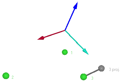
Intersect point
The intersect option means that the second axes will point in the direction of the specified point. However since the axes must be orthogonal, the second axes will actually intersect the projection of the point on the coordinate plane orthogonal to the first axes. The name of the orthogonal plane is displayed in the dialog.The example below displays the second axes defined by the projection of point 3 on the orthogonal plane defined by the line from point 1 to point 2.
-
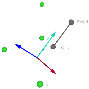
Parallel to the line from point
The parallel option means that the second axes will point in the direction from the first specified point to the second as projected on to the orthogonal plane to the first axes. The name of the orthogonal plane is displayed in the dialog.The example below displays the second axes defined by the projection of the line from point 3 to point 4 on the orthogonal plane defined by the line from point 1 to 2.
-