6DOF analog export
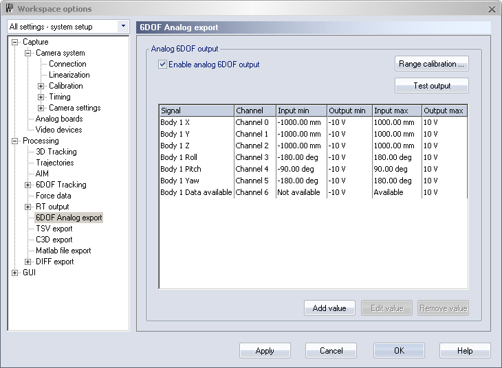
The 6DOF analog export page is only available if an analog output board (PCI-DAC6703) is installed in the measurement computer. With the analog export the information about 6DOF bodies’ positions can be used in feedback to an analog control system. Select the Enable analog 6DOF output option to enable the output of the board. The output will continue as long as the option is selected and the 6DOF body is being tracked.
The analog output board (PCI-DAC6703) is discontinued. Contact Qualisys support at support@qualisys.com for alternative solutions.
The list on the 6DOF Analog export page contains the wanted signals and their respective settings. Use Add value or double-click in the empty area to add a new signal, see chapter Analog channel settings. Use Edit value or double-click on the signal to change the settings of the selected signal. With Remove value the selected signals are removed from the list.
Before using the analog export you should set the Range calibration. Use the Test output option to test the output of the analog board.
Analog channel settings
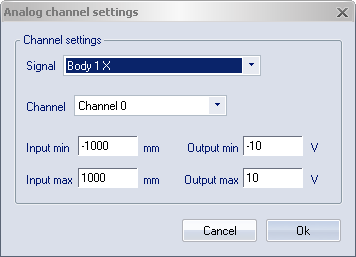
When clicking on Add value or Edit value the Analog channels settings dialog is displayed. In the dialog the following settings can be set:
-
Signal
The data in QTM that is used for the output signal. For each 6DOF body on the 6DOF bodies page there are seven available outputs: X, Y, Z, Roll, Pitch, Yaw and Data available. Data available shows whether the 6DOF body is visible or not.
The rotation angles will change if you change the Euler angles definitions.
-
Channel
The channel on the analog output board that will be used for the signal. Each channel can only have one signal assigned to it.
-
Input min/Input max
The minimum respectively the maximum value (mm or degrees) of the input data. If the input data is equal or smaller than the Input min the output of the channel is equal to the Output min. If the input data is equal or larger than the Input max the output of the channel is equal to the Output max.
For the three rotation angles the maximum input ranges depend on the ranges of the respective angle.
-
Output min/Output max
The minimum respectively the maximum value (V) of the output on the channel.
Data available has two positions Available and Not available instead of the input and output settings. Set the value in V which will be on the channel depending on whether the 6DOF body as seen or not.
Test output
When clicking on Test output the following dialog is opened.
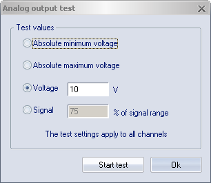
In the dialog four tests can be performed to test the output of the channels:
-
Absolute minimum voltage
The output of all channels are set to the minimum value of the analog board. This value should be entered on the Analog output range calibration dialog.
-
Absolute maximum voltage
The output of all channels are set to the maximum value of the analog board. This value should be entered on the Analog output range calibration dialog.
-
Voltage
The output of all channels are set to the specified voltage.
-
Signal % of signal range
The output of all channels is set to the specified percentage of the channel’s specified output range. If the channel is not used the output will be 0 V.
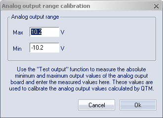
Range calibration
In the Analog output range calibration dialog the range of the specific board is entered to calibrate the output of the channels. The maximum and minimum values can be measured with the Test output option.