External timebase
Activate the External timebase with Yes on the Use external timebase setting. The external timebase setting applies to all cameras in the system, because it controls the capture rate of the cameras with an external signal. There are several ways to synchronize camera frames to an external timebase. For more information on how to use external timebase, see chapter How to use external timebase .
The external time base should be connected to the corresponding input connector of the Camera Sync Unit, see chapter Camera Sync Unit: front side.
When using an Oqus camera for synchronization the external timebase can either be connected via the Sync in connector of the splitter cable (see chapter Control connections), or the Sync in/Video in or Trig in/SMPTE in connector of the Oqus Sync Unit (see chapter Oqus Sync Unit). It is recommended that you connect the external timebase signal to the master camera.
It is important to use a stable signal source to achieve the best possible synchronization.
Qualisys video cameras can capture at a different frequency (a divisor) compared to the marker cameras, see chapter Using Qualisys video with External timebase.
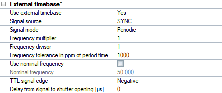
The following settings are available:
-
Use external timebase
Activate the use of an external timebase with Yes.
-
Signal source (Camera Sync Unit)
A Camera Sync Unit can be synchronized with the following signals. Make sure that the signal source is connected to the corresponding input connector on the Camera Sync Unit.
-
SYNC
Use a TTL signal to synchronize the system.
-
SMPTE
Use a SMPTE signal to synchronize the system.
The Use SMPTE timestamp option is activated automatically when selecting SMPTE as signal source.
-
GENLOCK
Use a video signal (black burst) to synchronize the system.
-
IRIG
Use an IRIG signal to synchronize the system.
IRIG cannot be used when there are any Oqus cameras included in the system.
-
Internal 100 Hz
The system is synchronized with an internal 100 Hz signal. This option will be automatically selected if 100 Hz continuous has been selected as Synchronization output mode on one of the synchronization output ports, see chapter Synchronization output.
-
-
Signal source (Oqus)
Oqus cameras can be synchronized with the following signals, where the corresponding settings differ some for the different signals:
-
Control port
Connect a TTL signal to the Sync in connector of the splitter cable or the Oqus Sync Unit. This is the standard method of synchronizing.
-
IR receiver
Send an IR signal which is received by the IR receiver on the front of the camera.
-
SMPTE
Use a SMPTE signal to synchronize the system. You need to use the Oqus Sync Unit to convert the signal, see chapter Using Oqus sync unit for synchronization.
The Use SMPTE timestamp option is activated automatically when selecting SMPTE as signal source.
-
Video Sync
Use a video signal (black burst) to synchronize. You need to use the Oqus Sync Unit to convert the signal, see chapter Using Oqus sync unit for synchronization.
-
Internal 100 Hz
The system is synchronized with an internal 100 Hz signal. This option can only be selected if 100 Hz continuous has been selected as Synchronization output on one of the cameras, see chapter Synchronization output.
This option is needed for the Twin system frame synchronization option, in which case it is selected automatically.
-
-
Signal mode
Select the way to synchronize the camera frame to the signal.
Not available for all choices of signal source.
-
Periodic
In this mode the system locks on to the signal of the external timebase. The capture frequency can be set as a multiplier/divisor. This is the recommended setting for periodic signals see chapter Using External timebase for synchronization to a periodic TTL signal.
-
Non-periodic
In this mode every single frame that is captured must be triggered by a signal from an external timebase source. This means that the frame rate is controlled by the external timebase source. To prevent that the QTM software indicates a timeout error, because no frames are captured, there is a Max expected time between two frames [s] setting. Set it to the largest possible interval between two consecutive signals from the external timebase source.
Notes on non-periodic signal mode:
-
The non-periodic sync cannot be faster than 120 Hz. This is because of network delays described in the Delay from signal to shutter opening setting below.
-
The minimum delay from signal to shutter opening is 19000 μs in non-periodic mode.
-
-
-
Frequency multiplier/divisor
Set the multiplier respectively divisor to multiply and divide the incoming sync signal.
-
Frequency tolerance in ppm of period time
Set the tolerance for jitter of external periodic signals in ppm of the period time. The period time of the external signal should not differ more than the specified tolerance for the system to lock on to the frequency.
Not available for the SMPTE signal.
-
Use nominal frequency
Activate the use of nominal frequency. When activated QTM will calculate the capture frequency based on the nominal frequency of the external timebase so that the relationship is always correct. This is recommended so that you can easily compare the data to that of an external system. If you do not use the nominal frequency, QTM will export the capture frequency with one decimal. In that case, the capture frequency may slightly deviate from what you expect due to the difference in clock speed between the Qualisys system and the external signal generator.
-
Nominal frequency
Enter the nominal frequency of the external timebase signal.
When using SMPTE as signal source the nominal frequency value is read from the SMPTE frequency setting under Timestamp.
-
TTL signal edge
Specify the signal edge used for synchronization, either negative (falling edge) or positive (rising edge).
-
Delay from signal to shutter opening
Specify the delay of camera exposure relative to the synchronization signal in microseconds. For the Periodic mode the delay is 0 by default and can be set to any value. For SMPTE as a signal source the minimum delay is 100 μs.
For the Non-periodic mode the default and minimum time is 19 ms. This is because there must be enough time for the trigger packet to reach all of the cameras in the system. Which means that there is always a delay between the signal and the actual capture. If it is set too short all of the cameras will not receive the TCP/IP message and the synchronization will be lost. To not have to consider the delay set it to the same as the period of your signal. In this way you will not get an image for the very first trigger event but for all the following the capture will be made at the same time as the synchronization signal.
-
Max expected time between two frames [s]
This setting is only active for the Non-periodic mode. Then it decides the maximum time QTM waits for the next frame, i.e. the longest possible time between two signals from the external timebase.
The camera system can be damaged if the hardware setup is not done properly. Make sure that the resulting camera frequency never exceeds the maximum frequency of the cameras in the current mode. The frequency should be limited to 97.5% of the maximum frequency at full image size. For an overview of maximum frequencies per camera, see Qualisys camera sensor specifications (marker mode).