Using Oqus sync unit for synchronization
By connecting the Oqus sync unit to the master camera in the Oqus system, you can use an SMPTE signal to timestamp and synchronize the measurements. The sync unit can also handle a video signal (black burst or tri-level) for synchronization (also called genlock). For more information about how the synchronization works in sound applications see chapter Using SMPTE for synchronization with audio recordings.
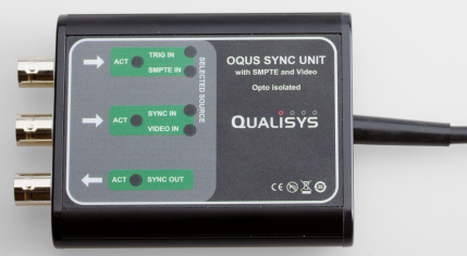
The sync unit has the following opto-isolated connections.
-
Trig in/SMPTE in
This connection is used either as the standard Trig in connection or to convert the SMPTE signal to a signal compatible with the Oqus camera. The SMPTE signal can be used for both timestamp and synchronization. The LEDs next to connector will indicate which input you are using in QTM.
For the best detection of the SMPTE timecode use one of the Analog outputs on the Motu device so that you can increase the amplitude of the signal. Move the dial in the SMPTE program so that it is pointing right to get a high enough amplitude. The SMPTE timecode output on the MOTU device is often too low for the Sync unit to get a stable detection of the SMPTE timecode.
-
Timestamp
To activate the SMPTE timestamp open the Synchronization page in the Project options dialog. Then select Use SMPTE timestamp below the SMPTE heading also make sure that you select the correct SMPTE frequency, see chapter Timestamp.
-
-
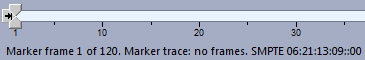
The timestamp is displayed in the Timeline control bar. Because the timestamp is sampled at for example 30 Hz there can be several frames per timestamp. Which is indicated by the last number (subframes) after '::' in the timestamp.
-
Synchronization
To activate the SMPTE synchronization open the Synchronization page in the Project options dialog. Then select SMPTE as Signal source below the SMPTE heading, see chapter External timebase.
Remember to select the correct SMPTE frequency under the SMPTE heading.
-
-
Sync in/Video in
The connector can be used either for Sync in or Video in synchronization. The LEDs next to connector will indicate which input you are using in QTM.
-
Sync in
The Sync in connection is standard connector for an external timebase connection, see chapter External timebase and Using External timebase for synchronization to a periodic TTL signal. For example the word clock of up to 48 kHz from a sound sampling board can be connected to this connection and then divided to the wanted frequency on the Synchronization page in the Project options dialog. Make sure that you have set a divisor that gives a camera frequency that works with the Oqus camera.
If you use SMPTE for timestamp and another external signal for synchronization, both must be connected to the same camera.
-
Video in
To activate the video synchronization open the Synchronization page and select Video sync on the Control port setting, see chapter External timebase. When the Video in option is selected the sync unit will decode a black burst or tri-level video signal so that the Oqus camera can lock in on the signal. Just as for the standard sync-in you need to have time reference to know when the measurement starts, for example you can use the SMPTE signal.
-
-
Sync out
This is the standard Sync out connection from the camera, see chapter Synchronization output and Using Sync out for synchronization.