Description of Camera Sync Unit
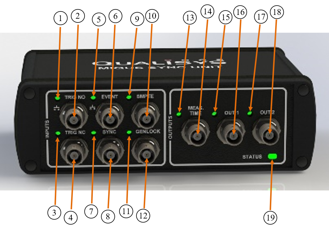
Camera Sync Unit: front side
-
Trig NO indicator
Turns on for 0.5 s when the Trig NO input transitions from high to low. -
Trig NO input
Trigger input (TTL, 0-5 Volt, normally open). The base voltage of the port is 5 Volt (high). -
Trig NC indicator
Turns on for 0.5 s when the Trig NC input transitions from low to high. -
Trig NC input
Trigger input (TTL, 0-5 Volt, normally closed). The base voltage of the port is 0 Volt (low). -
Event indicator
Turns on for 0.5 s when the Event input transitions from high to low. -
Event input
Input for creating events in QTM. The base voltage of the port is 5 Volt (high). -
Sync indicator
Turns on for 0.5 s when the Sync input transitions from low to high. -
Sync input
Input for TTL synchronization signal (0-5 Volt). The base voltage of the port is 0 Volt (low). -
SMPTE indicator
Turns on when a valid SMPTE signal is present at the SMPTE input. -
SMPTE input
Input for SMPTE time code signal, e.g. from a MOTU sound device. -
Genlock indicator
Turns on 0.5 s for each vsync frame when a valid video signal is present at the Genlock input. -
Genlock input (video)
Genlock input for synchronization to a video signal. Compatible with Composite video (s-video) and Component video (YPbPr / GBR). -
Measurement time indicator
Turns on 0.5 s at the start of a measurement. -
Measurement time output
Outputs a pulse that lasts for the duration of the measurement. -
Output 1 indicator
Turns on for 0.5 s when the Output 1 port transitions from low to high. -
Output 1
Programmable synchronization output (TTL, 0-5 Volt). -
Output 2 indicator
Turns on for 0.5 s when the Output 2 port transitions from low to high. -
Output 2
Programmable synchronization output (TTL, 0-5 Volt). -
Measurement status indicator
-
Green light: The system is ready to start a measurement.
-
Yellow light: The system is measuring.
-
Flashing green light: The device is synchronizing to the master device.
-
Flashing red light: Error signal.
-
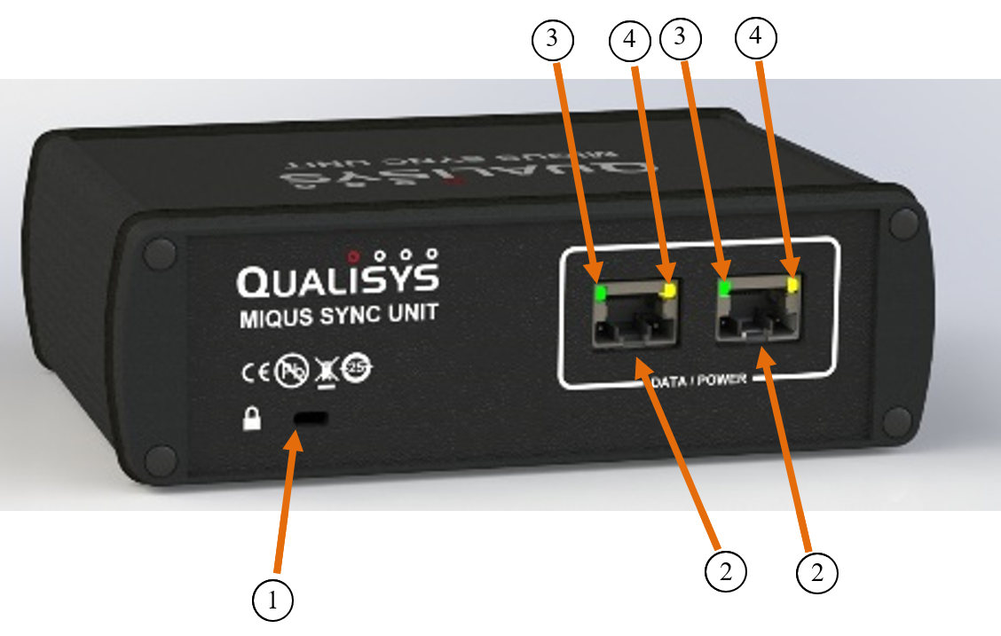
Camera Sync Unit: back side
-
Kensington Security Slot
Slot for connecting a security cable. -
Daisy-chain data/power port
Combined Power/Gigabit Ethernet connector. -
Power/Gigabit Link indicator
Lit green when the Sync unit is powered on. An additional orange LED is lit when a Gigabit link is established. -
Link/Activity indicator
Shows the status of the Ethernet connection. Fixed yellow light means that a carrier signal has been sensed and that the connection is up. Flashing yellow light indicates that data is received and/or transmitted.