Description of Oqus devices
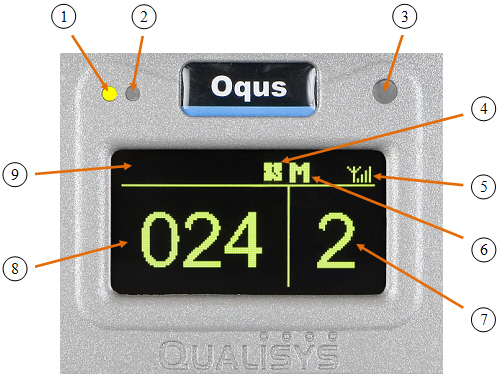
Oqus camera display
The Oqus camera has a large graphical OLED display and three LEDs on the front to inform the user of the current status of the camera. The display shows, among other things, the camera number and the number of markers currently seen by the camera.
The display will be turned off when the camera enters stand-by mode, i.e. if the camera has not been in use for 2 hours. Start a preview in QTM to light up the display again.
-
Measurement status indicator
Green light - The camera is ready to start a measurement
Yellow light - The camera is measuring
Flashing green light - Waiting for trigger to start measurement
Flashing yellow light - Waiting for trigger to switch from pre-trigger to post-trigger measurement -
Error indicator
A red light indicates that an error has occurred. The LED is blinking when a software error occurs and is lit constantly if a hardware error occurs. -
IR receiver
The IR receiver is used for synchronization with certain active markers. It detects modulated light with a frequency of 33 kHz and is sensitive to light with wavelengths between 800 and 1100nm. -
Synchronization status
During the synchronization phase this symbol is flashing. When the camera is synchronized with the master camera in the system it becomes stable. -
WLAN indicator
This symbol is displayed when the WLAN of the camera is activated. -
Master/Slave indicator
An M indicates that the camera is master for the system and by that controls for example internal synchronization. An S indicates that the camera is a slave. The indicator can also be a rotating + sign, which means that the camera is looking for the Master camera. -
Camera number
The area to the right usually shows the camera number that the camera has in QTM. The camera number can be changed with the Reorder tool in the 2D view window. This number is stored in the camera so it is shown at the next camera startup.If the camera has never been connected to QTM the last three digits of the serial number (upper part) and the last octet of the IP-number assigned to the camera (lower part) will be shown instead. This can also be activated from the QDS menu, see QDS.
-
Marker area
During a marker measurement this area shows the number of markers currently seen by the camera. When the camera is idle or is collecting video, this area shows ’-----’. -
Text area
This area is used for scrolling text messages, for example during startup.
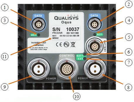
Oqus camera connectors
The back of the camera holds six connectors for power, data and control connections. The view differs slightly depending on the type of camera. The image below shows the standard version of the camera. The water protected version uses different connectors and lacks the LEDs found on the standard version.
-
Left Data port (light blue)
Ethernet connector. 100BaseTX/802.3i, 100 Mbps, Fast Ethernet. -
Right Data port (light blue)
Identical to the left data port. -
Left Ethernet activity indicator
Shows the status of the Ethernet connection. Fixed green light means that a carrier signal has been detected and that the connection is up. Flashing green light indicates that data is received and/or transmitted. -
Right Ethernet activity indicator
Identical to the left indicator. -
Battery port (white)
Used to supply the camera with power from an Oqus compatible battery. -
Battery status indicator
Lit green when the camera is supplied though the BATTERY port.
Lit red when a voltage outside the specified range (10-16V) is connected to the port. -
Power supply status
Lit green when the camera is powered through one of the POWER ports. A red light indicates internal power supply error. -
Right power supply port (black)
Daisy-chain power port. Supplies the camera with 48VDC and can be daisy chained to supply cameras further down the chain with power. -
Left power supply port (black)
Identical to the right power supply connector. -
Control port (light grey)
The control port is used to synchronize the camera with external sources, and contains pins for among other things external trigger in, external sync in and external sync out. Splitter cables are needed to connect one or more BNC cables to this port, for more information see Control connections. -
Camera identification
This label provides information on:-
The serial number of the camera.
-
The product number.
-
The Ethernet Mac address.
-
The WLAN Mac address.
-
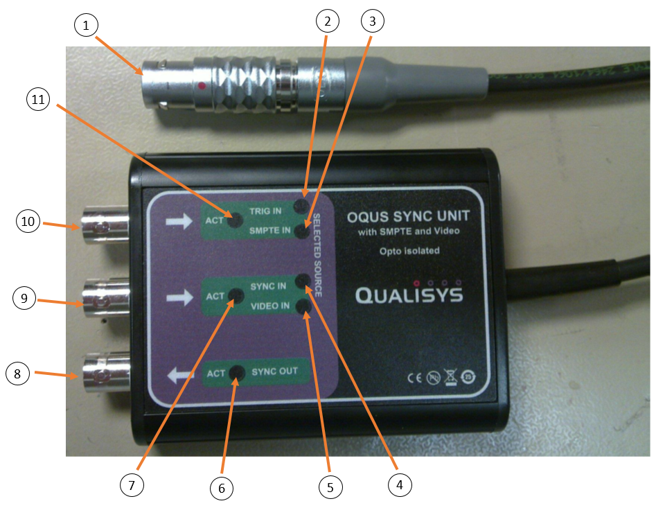
Oqus Sync Unit
-
Oqus connector
Connector for control port on an Oqus camera. -
Trig In indicator
Lit when in Trig in mode. -
SMPTE indicator
Lit when in SMPTE mode. -
Sync In indicator
Lit when in Sync in mode. -
Video In indicator
Lit when in Video/Genlock mode. -
Sync out activity indicator
Lit green for 0.5 s when output transitions from high to low. -
Sync in activity indicator
Lit green for 0.5 s when signal transitions from high to low. -
Sync output
Programmable synchronization output (TTL, 0-5 Volt). -
Sync input/Genlock (video) input
Mode dependent on Signal source selected in QTM (see chapter External timebase).-
Sync input (TTL, 0-5 Volt) when Signal source set to Control port.
-
Video input when Signal source set to Video sync. Compatible with Composite video (s-video) and Component video (YPbPr / GBR).
-
-
Trig input
Mode dependent on QTM project settings.-
Trigger input (TTL, 0-5 Volt) when in Trig in mode (default).
-
SMPTE timecode input (e.g. from a MOTU sound device) when in SMPTE mode (Signal source set to SMPTE or Use SMPTE timestamp activated, see chapters External timebase and Timestamp).
-
-
Trig in activity indicator
Lit green for 0.5 s when signal transitions from high to low, or continuously lit when a valid SMPTE signal is present.