Transformation of calibration
The origin and orientation of the global coordinate system obtained with a calibration can be changed via the Transformation page.
Depending on if you want to apply a translation, a rotation or both, check the respective checkboxes and specify the values. You can either manually specify the values for translation or rotation, or use one of the automated methods to extract the translation and/or the rotation values from a measurement. The following methods are available:
-
Rotate axis to line
-
Transform coordinate system to rigid body
For more information about these methods and examples of scenarios in which they can be useful, see the chapters below.
The transformations obtained with the automated methods are based on the used calibration and dependent on the exact placement of the L-frame. It is recommended to redo the transformation for every individual calibration.
Rotate axis to line
With the Rotate axis to line function a line can be used to define the direction of one of the axes. This can for example be useful to define the vertical axis to coincide with the direction of gravity using a plumb line with markers. Follow this procedure to use the function:
-
Make a measurement with two static markers along the axis you want to align. It is important that the markers are as static as possible.
Make sure that the file uses the same calibration as the one currently loaded in the project.
-
Keep the file open and go to the Transformation page in the Project options dialog. If the Transformation page is not active go to the Calibration page and check the Apply coordinate transformation box.
-
Activate the Rotate coordinate system option on the Transformation page.
-
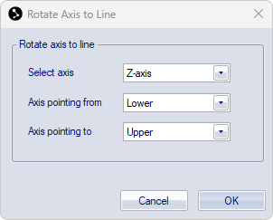
Click on the Rotate axis to line button to open the Rotate axis to line dialog.
-
Under Select axis, select the axis that you want to align with the markers.
-
Select the trajectories of the respective markers corresponding to the axis under Axis pointing from and Axis pointing to.
-
Click OK to calculate the rotation. This will update the values under Rotate coordinate system, based on the average positions of the selected trajectories across the selected range in the file.
-
In the Coordinate system dialog, choose if the new transformation should be applied to the current calibration (Yes) or apply to following calibrations (No).
When choosing Yes, a new calibration file with suffix "-transformed" will be saved in the Calibration folder and loaded as current calibration into the project.
To apply the transformation to an existing file, you must reprocess the file with the new transformed calibration.
Notes on Rotate axis to line:
-
This method only affects the rotation of the coordinate system, not the position.
-
The orientation of the unselected axes is also affected.
Transform coordinate system to rigid body
The position and rotation of a rigid body can be used to define the global coordinate system. This can for example be useful in the following situations:
-
Alignment of the global coordinate system with the floor (floor calibration),
-
Use a reference rigid body to ensure a consistent global coordinate system, independent of the position of the L-frame during individual calibrations.
The methods are outlined in the chapters below.
Floor calibration
Calibration of the floor level can be useful when it is not possible to level the L-frame, or for improving the floor level for large volumes.
If you are using force plates, you must recalculate the force plate positions after performing a floor calibration.
To align the global coordinate system with the floor, follow the steps below:
-
Place markers to define the floor:
-
Place at least three markers on the floor spanning the floor area of interest.
-
Do a short capture.
-
Open the file and create a rigid body from the floor markers.
-
Use the Align the body using its points option to define the rigid body as a horizontal plane, see chapter Rotate body.
-
Check that the new rigid body definition is correct. It is usually easiest to do this in preview mode.
To apply the new rigid body definition to the file, you must reprocess the file with 6DOF Tracking settings from the project.
-
-
Start a preview, and make sure that the rigid body is tracked.
-
Alternatively, you can use the reprocessed file from the previous step.
When using a file, make sure it is based on the same calibration as the one currently loaded in the project.
-
-
Go to the Transformation page in the Project options dialog. If the Transformation page is not active go to the Calibration page and check the Apply coordinate transformation box.
-
Check the Rotate coordinate system options on the Transformation page.
Do not check the Translate origin option, since this will result in an offset of the floor to the measured height of the markers.
-
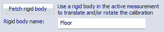
Type the name of the rigid body in the Rigid Body name text box.
-
Click on the Fetch rigid body button. This will update the values under Rotate coordinate system, based on the current frame.
If the coordinate system already included an earlier transformation, the values will be relative to the untransformed coordinate system.
-
Click OK or Apply to start using the transformation.
-
In the Coordinate system dialog, choose if the new transformation should be applied to the current calibration (Yes) or apply to following calibrations (No).
When choosing Yes, a new calibration file with suffix "-transformed" will be saved in the Calibration folder and loaded as current calibration into the project.
To apply the transformation to an existing file, you must reprocess the file with the new calibration.
Use a reference rigid body to define the global coordinate system
In situations where you need a well defined coordinate system for the lab, but it is not possible to consistently place the L-frame in the exact same position, using a reference rigid body may be a good alternative to define the global coordinate system through the Fetch rigid body transformation method. This can be especially useful for large volumes, in which a small deviation of the orientation of the L-frame can have a significant effect on the measured coordinate values in locations far away from the L-frame.
To create a reference rigid body, the markers need to be in fixed positions. If you need to remove the markers during the measurements, make sure that you can put them back in the exact same positions again, for example by using threaded markers and screw holes at fixed locations.
If you can configure the reference markers into the shape of a custom L-frame, you can use them directly for a calibration, if needed in combination with a fixed transformation. In this case, you need to specify the marker distances in the Reference object definition for a custom calibration kit on the Calibration page under the Project options.
For other marker configurations, you need to calibrate with the standard L-frame and use the reference rigid body to apply the transformation as outlined in the instructions below.
Create the reference rigid body definition
-
Place markers taking into account the following criteria:
-
They should be well visible to the cameras,
-
Spread the markers across a large part of the volume to obtain a high precision of the orientation.
-
-
Optionally, use markers in specific landmark positions to define the origin or specific axes.
-
Create a rigid body and use the landmark markers to set up the local rigid body definition as the global coordinate system you want to use, see chapter Definition of local coordinate system.
-
Optionally, remove any markers that are in positions that may be difficult to track from the rigid body definition, keeping only the tracking markers.
-
Save the rigid body definition for later use.
Do a calibration and apply the transformation
-
Place L-frame in an arbitrary location and perform a calibration.
-
Position the tracking markers of the reference rigid body.
-
Load the reference rigid body on the 6DOF Tracking page under the Project options.
-
Start a preview or do a capture and open it.
-
Go to the Transformation page in the Project options dialog. If the Transformation page is not active go to the Calibration page and check the Apply coordinate transformation box.
-
Activate the Translate origin and Rotate coordinate system options on the Transformation page.
-
Type the name of the rigid body in the Rigid Body name text box.
-
Click on the Fetch rigid body button. This will update the values under Translate origin and Rotate coordinate system, based on the current frame.
If the coordinate system already included an earlier transformation, the values will be relative to the untransformed coordinate system.
-
Click OK or Apply to start using the transformation.
-
In the Coordinate system dialog, choose Yes to apply the new transformation to the current calibration. A new calibration file with suffix "-transformed" will be saved in the Calibration folder and loaded as current calibration into the project.
To apply the transformation to an existing file, you must reprocess the file with the new calibration.