Wand calibration
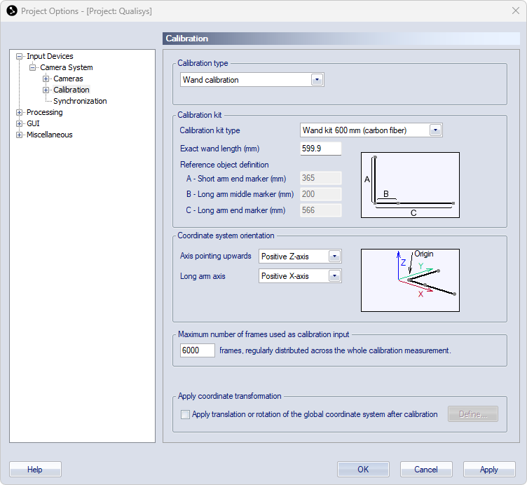
The wand calibration method requires two calibration objects to calibrate the system. The first is the L-frame, a stationary L-shaped reference structure with four markers attached to it. The L-frame defines the origin and orientation of the coordinate system that is to be used with the camera system. The other calibration object is called calibration wand. It consists of two markers located a fixed distance from each other. The wand is moved in the measurement volume to generate data to determine the locations and orientations of the cameras. For more information about how to use the wand calibration method, see chapter Wand calibration method.
The calibration objects are part of the measurement equipment and should be treated with care. A scaling error derived from a damaged calibration object will propagate throughout the whole measurement and analysis.
Calibration type
Under the Calibration type, you can choose the following options:
-
Calibration type
Make sure that Calibration type is set to Wand calibration if you want to use this calibration method.
-
Linearization
-
Use linearizations loaded in project/file: Use the linearizations that are currently loaded in the project. This allows you to use linearization files that differ from the linearizations that are stored in the cameras.
-
Use factory linearizations: Use the linearizations from the cameras.
For more information on the choice of linearization files, see chapter Choice of linearizations.
-
Calibration kit
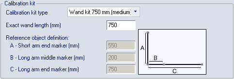
Define the calibration kit you are using under the Calibration kit heading.
-
Calibration kit type
By choosing the Calibration kit type in the drop-down box the size of the L-frame is specified. The calibration algorithms will then find the reference markers when the calibration recording is made.
The calibration kit is set to --- Select kit --- when creating a new project with default settings.
The alternatives refers to the length and material of the wand that is used in combination with the L-shaped structure. The following settings are available for Calibration kit type:
-
Active wand kit 500 mm
-
Active wand kit 1011 mm
-
Wand kit 110 mm
-
Wand kit 120 mm
-
Wand kit 300 mm
-
Wand kit 300 mm (carbon fiber)
-
Wand kit 600 mm (carbon fiber)
-
Wand kit 750 mm
-
Kit defined below
Use this type if you are using a custom L-frame, and specify the L-frame dimensions under Reference object definition.
For detailed information about specific calibration kits, see chapter Qualisys calibration kits.
-
-
Exact wand length
Enter the distance between the centers of the reflective markers on the reference wand in Exact wand length. It has been measured with high accuracy and can be found on a plate on the wand.
-
Reference object definition
For Qualisys calibration kits, the Reference object definition displays the distances between the markers on the L-frame. When choosing Kit defined below as Calibration kit type, you must specify the distances between the centers of the markers of the custom L-frame.
The requirements for the configuration of a custom L-frame are:
-
The distance A should be shorter than the distance C.
-
The distance B should be less than half the distance C.
-
Coordinate system orientation
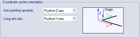
Under the Coordinate system orientation heading the coordinate system of the motion capture can be customized by choosing the way the X-, Y- and Z-axes are orientated relative to the L-frame.
Axis pointing upwards and Long arm axis are the settings which decide the directions of the axes. Select the axis that you want for each setting to get the desired coordinate system, see the figure next to the settings to understand how the axes are orientated.
Maximum number of frames used as calibration input
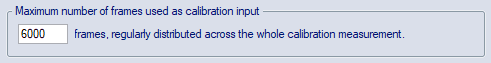
The Maximum number of frames used as calibration input setting limits the number of frames used in the calibration process. The default value is 6000 frames. If the number of frames in the calibration file is larger than this setting, the frames will distributed evenly across the whole measurement.
Increase this value if you have a large volume, especially if the volume is an extended volume where not all of the cameras can see the L-frame. To test this make a long calibration and test with different Maximum number of frames to see how it affects your calibration result. You can increase this value to as many frames as you like, at the expense of longer processing times for the calibration.
For more information about the calibration time and the frequency that are used see chapter Calibration dialog.
Apply coordinate transformation
![]()
With Apply coordinate transformation you can translate and rotate the global coordinate system to any desired position. Select the checkbox and then click Define to set the coordinate transformations on the Transformation page, see chapter Transformation.