Transformation
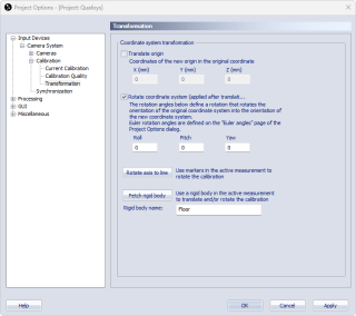
The Transformation page contains the settings for defining a new global coordinate system. The two changes that can be made to the coordinate system is Translate origin and Rotate coordinate system. By changing these parameters you can in fact move and turn the coordinate system to any position and orientation. The change is always related to the original position and orientation of the calibration coordinate system. In the case of the Fixed camera calibration this means the origin of the survey measurement.
A new calibration file is saved if you apply a new transformation to the current calibration. This file only includes calibration data and no 2D data. Therefore, you must always go back to the first calibration if you need to recalibrate.
To activate the change you must select the checkbox of respective setting.
-
Translate origin (X(mm), Y(mm), Z(mm))
Enter the new position of the origin of the coordinate system (in mm). The direction of the parameters (X, Y and Z) is always related to the original coordinate system of the calibration. -
Rotate coordinate system (Roll, Pitch, Yaw)
Enter the new rotation of the coordinate system (in degrees). The rotations always refer to the original coordinate system and they are always applied from left to right. To which axes the rotations are applied depends on the Euler angles definitions on the Euler angles page, see chapter Euler angles. -
Use the Rotate axis to line or Fetch rigid body buttons to define the rotation from a measured line or a rigid body, see chapters Rotate axis to line and Transform coordinate system to rigid body (floor calibration).
Notes about rotations:
-
If the Euler angles are changed after a transformation, the transformed coordinate system will have the same orientation as before but the rotation parameters on the Transformation page will change to reflect the new definition.
-
The rotation angles are used to calculate a rotation matrix, which is then used to transform the coordinate system. When the resulting rotation matrix is converted back to rotation angles again it is not necessarily the same angles. This means that the angles that you have entered can change after you have applied it to the coordinate system. E.g. if you just enter a pitch of 100 degrees (using Qualisys standard) this will result in the angles roll = 180°, pitch =80°, yaw =180°.
If you use a custom bounding box on the 3D Tracking page, or if you are using a force plate, these will be moved with the transformation and the positions must therefore be re-entered.
Rotate axis to line
With the Rotate axis to line function a line can be used to define the direction of one of the axes. This can for example be useful to define a vertical or horizontal axis if the floor is not level enough. Follow this procedure to use the function:
-
Make a measurement with two static markers that defines the line that you want. It is important that the markers are as static as possible, because an average is used to define the line.
Make sure that the file uses the same calibration as the one currently loaded in the project..
-
Keep the file open and go to the Transform page in the Project options dialog. If the Transform page is not active go to the Calibration page and check the Apply coordinate transformation box.
-
Activate the Rotate coordinate system option on the Transformation page.
-
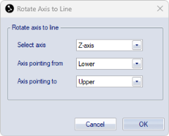
Click on the Rotate axis to line button to open the Rotate axis to line dialog.
-
Select the axis that you want to define the rotation for.
-
Then select the trajectory that the Axis is pointing from and the trajectory that the Axis pointing to.
-
Click OK to calculate the rotation. This will update the values under Rotate coordinate system, based on the average positions of the selected trajectories across the selected range in the file.
-
In the Coordinate system dialog, choose if the new transformation should be applied to the current calibration (Yes) or apply to following calibrations (No).
When choosing Yes, a new calibration file with suffix "-transformed" will be saved in the Calibration folder and loaded as current calibration into the project.
To apply the transformation to an existing file, you must reprocess the file with the new calibration.
Notes on Rotate axis to line:
-
This method only affects the rotation of the coordinate system, not the position.
-
The rotation of the unselected axes is also affected.
Transform coordinate system to rigid body (floor calibration)
The position and rotation of a rigid body can be used to define the global coordinate system. This can for example be used to align the global coordinate system with the floor. Follow this procedure to use the function:
-
Make a measurement with a rigid body or track the rigid body in preview mode. Make sure that you define the rigid body coordinate system according to your requirements. For example for a floor calibration, follow these steps to create the rigid body:
-
Place 4 markers on the floor close to the corner of the measurement volume.
-
Define a rigid body from these four markers.
-
Use the Translate and Rotate options on the 6DOF Tracking page to achieve the desired definition. Use the Align the body using its points option to define a plane, see chapter Rotate body.
-
Check that the new rigid body definition is correct. It is usually easiest to do this in preview mode.
-
-
Open the file or start a preview, and make sure that the rigid body is tracked.
When using a file, make sure it is based on the same calibration as the one currently loaded in the project.
-
Go to the Transform page in the Project options dialog. If the Transform page is not active go to the Calibration page and check the Apply coordinate transformation box.
-
Activate the Translate origin and/or Rotate coordinate system options on the Transformation page. For a floor calibration you usually only need to specify the rotation.
-
Type the name of the rigid body in the Rigid Body name text box.
-
Click on the Fetch rigid body button to update the values under Translate origin and/or Rotate coordinate system. This will update the values under Translate origin and/or Rotate coordinate system, based on the current frame. If the coordinate system already included an earlier transformation, the values will be relative to the untransformed coordinate system.
-
Click OK or Apply to start using the transformation.
-
In the Coordinate system dialog, choose if the new transformation should be applied to the current calibration (Yes) or apply to following calibrations (No).
When choosing Yes, a new calibration file with suffix "-transformed" will be saved in the Calibration folder and loaded as current calibration into the project.
To apply the transformation to an existing file, you must reprocess the file with the new calibration.


