Trajectory info window menu
The Trajectory info window menu contains options for the tracked trajectories in a file. Most of the options are not available in real-time. The menu can be accessed by right-clicking in the following places:
- On a trajectory or a part in one of the Trajectory info windows.
- On a marker or a trace in a 3D view window.
- It is also available on the Edit menu.
When multiple trajectories are selected the options on the menu is applied to all of the trajectories. The following options are available on the menu:
-
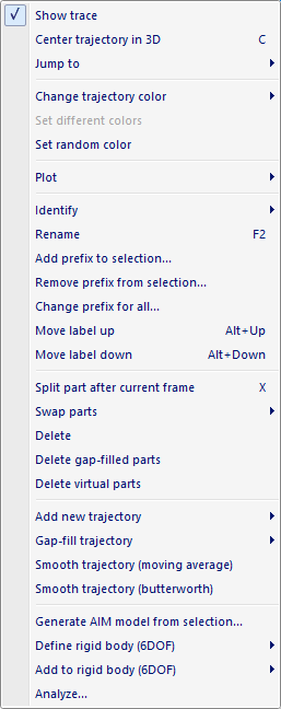
Show trace
Toggle the display of the trace of the selected trajectories.There are also settings for the display of traces on the 3D view settings page in Project options.
-
Center trajectory in 3D
Center the 3D view on the selected trajectory or part. The time will be moved to the first frame of the selected marker, if the trajectory is not visible in the current frame.This option is available in RT/preview mode.
-
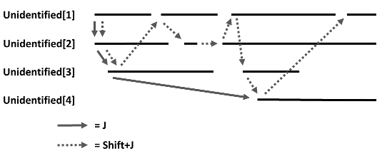
Jump to
Jump in time to the next unidentified trajectory or part (see illustration below). The trajectory or part is selected and the 3D view is centered.-
Next unidentified trajectory
Jump to the next unidentified trajectory (keyboard shortcut J). -
Next unidentified part
Jump to the next unidentified part (keyboard shortcut Shift+J) -

-
-
Change trajectory color
Change the color of the selected trajectories. -
Set different colors
Change the color of the selected trajectories to different colors. It steps through 256 colors, but with different steps depending on the number of trajectories. -
Set random color
Change the color of the selected trajectories to random colors, this can result in similar colors. -
Plot
Plot the 3D data of the selected trajectories, see chapter Plot 3D data.This option is available in RT/preview mode.
-
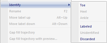
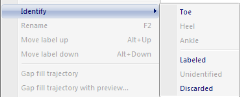
Identify
Identify a selected trajectory by choosing an available label from the list. If you have selected multiple trajectories, you can move them to another Trajectory info window. -
-
Rename
Rename the selected trajectory. This is the same as double-clicking on the label.This option can only be used on one trajectory at a time.
-
Add prefix to selection...
Add a prefix to the selected trajectories. -
Remove prefix from selection...
Remove a prefix from the selected trajectories. -
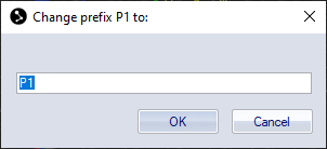
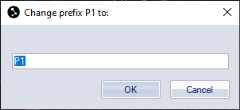
Change prefix for all...
Change the prefix for all trajectories with the same prefix as the selected trajectory. Note that the prefix separator must be an underscore so that QTM can detect what to change. In the dialog replace the current prefix with the new prefix. Do not add an underscore at the end. -
-
Move label up
Move the label up one step in the Labeled trajectories list. -
Move label down
Move the label down one step in the Labeled trajectories list. -
Split part after current frame
Split a trajectory or part of a trajectory after the current frame into two parts, see chapter Split part after current frame. -
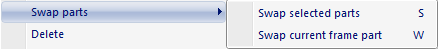
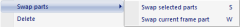
Swap parts
Swap parts between two selected trajectories, see chapter Swap parts.The parts that are swapped must not overlap any other parts in the trajectories.
-
-
Swap all parts
Swap all selected parts in the two trajectories (keyboard shortcut: S). -
Swap current frame part
Swap the parts of the current frame in the two trajectories (keyboard shortcut: W).
-
-
Delete
Delete the selected trajectories or parts. If you delete a trajectory in the Labeled trajectories window, it is moved to the Unidentified trajectories window. More information see chapter Delete trajectories. -
Delete gap-filled parts
Delete the gap-filled parts of the selected trajectories or parts. -
Delete virtual parts
Delete virtual parts of the selected trajectories or parts. -
Add new trajectory
Add a new trajectory. The options are:-
Empty: Create a new empty trajectory.
-
Virtual (Average of selected trajectories): Create a new virtual trajectory based on the geometrical average of the currently selected trajectories.
-
Virtual (Static from current frame): Create one or more new static virtual trajectories at the current frame position of the currently selected trajectory or trajectories.
-
-
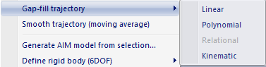
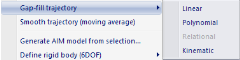
Gap-fill trajectory
Fill the gaps of the selected trajectories using one of the following gap-fill methods.-
-
Linear
Fill the gaps of the selected trajectories using linear gap filling. -
Polynomial
Fill the gaps of the selected trajectories using polynomial gap filling. The maximum gap size is set to the Max frame gap setting under Project Options, Trajectories (default 10 frames) used at the time the file was being processed. For gap filling single trajectories with alternative gap fill settings or methods, see chapter Filling of gaps. -
Relational
Apply gap filling of relational type according to the order of the selection. There is no maximum gap limitation. The selection order is as follows:-
Trajectory to be filled (required)
-
Trajectory used as origin (required)
-
Trajectory used to define the X axis
-
Trajectory used to the define the XY-plane
-
-
For more information about relational gap filling, see chapter Filling of gaps.
-
Relational (Rigid body)
Apply relational gap-filling to trajectories which are in a rigid relation to each other. Select at least four markers to apply Rigid body relational gap-fill. Gaps in any of the selected trajectories are filled using the relation to the other trajectories. If there are overlapping gaps in some of the trajectories then they are not gap-filled. -
Kinematic
Fill gaps of selected trajectories using kinematic gap filling based on current skeleton data. The selected trajectories must be included in a skeleton definition.
-
-
Smooth trajectory (moving average)
Apply moving average smoothing to selected trajectories. The window size is taken from the Smooth settings in the Settings sidebar of the Trajectory Editor window, see chapter Settings sidebar. -
Smooth trajectory (butterworth)
Apply butterworth smoothing to selected trajectories. The cutoff frequency is taken from the Smooth settings in the Settings sidebar of the Trajectory Editor window, see chapter Settings sidebar. -
Generate AIM model from selection
Generate an AIM model using the currently selected trajectories only. For more information, see chapter Generating an AIM model. -
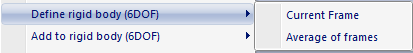
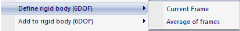
Define rigid body (6DOF)
Create a new 6DOF body on the 6DOF bodies page. The available options are:-
-
Current Frame: Create rigid body definition of selected trajectories based on the current frame. This method is automatically applied when in Preview mode.
-
Average of frames: Create rigid body definition based on the average relative positions of the selected trajectories across the capture. The advantage of this method is that the statistics of the marker positions are taken into account. The Bone tolerance setting of the body will be based on these statistics.
-
-
The 6DOF body will be added both to the 6DOF Tracking page in Project Options and in the current file. The origin of the rigid body will be the geometric average of the included marker positions. The orientation corresponds to the orientation of the rigid body at the first frame of the file.
Make sure that the body includes at least three points.
The trajectories will keep their label name unless they are named 'New XXXX' or are unidentified.
-
Add to rigid body (6DOF)
Add current frame positions of selected markers to a rigid body. The point(s) will be added to the rigid body definition in the current file and to that in the Project Options if it exists. -
Analyze…
Calculate parameters from the 3D data and/or filter the 3D data, see chapter Analyze. Analysis can also be accessed from the Analyze trajectory button on the AIM toolbar.