Gaps
Gaps are to be understood as missing parts within a trajectory. Two common types of gaps are:
- Gaps due to incomplete identification.
- Gaps due to missing 3D data, for example in case of occlusions,
The first type of gaps can generally be kept to a minimum by improving the AIM model. In some cases, manual identification may be needed to add unidentified parts to the trajectory. Remaining gaps of the second type can be detected and filled in the Trajectory Editor.
Identification and selection of gaps
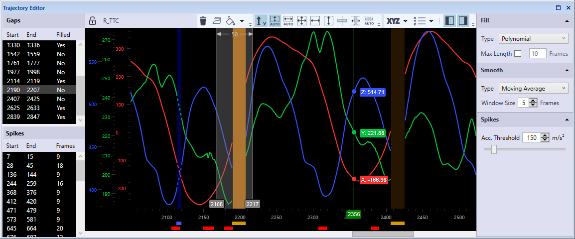
Gaps are indicated in the plot area by a brown area and an amber indicator below the time axis at the frames where data is missing. The gaps are also listed in the Gaps panel in the Points of Interest sidebar.
You can select a gap in the graph by clicking on the gap area. The selection range is then set from the start to the end of the gap, and the gap area will be highlighted.
Alternatively, you can select gaps in the Gaps panel in the Points of Interest sidebar. By holding the Shift key you can select multiple gaps. The selection range is then set from the start of the first gap to the end of the last gap. When double clicking on a gap in the Gaps panel, the current frame will be moved to the start of the selection.
Filling of gaps
To fill gaps follow these steps:
-
Select the trajectory you want to edit. You can select the trajectory in one of the Trajectory info windows, or by clicking on the marker in the 3D view window.
-
Select a gap or a frame range that includes the gaps you want to fill.
-
Press the Fill button.
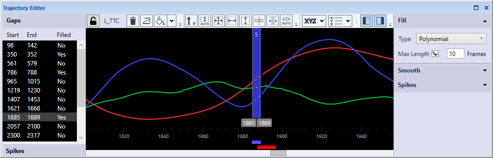
The gaps included in the selected range will then be filled using the Type specified in the Fill settings. The filled parts are indicated in the plot area by a dark blue area and a blue line below the time axis at the gap-filled frames, and the data series is shown as a dashed line.
The available fill types can be divided into two categories. Linear, Polynomial, Relational and Kinematic are gap fill types that interpolate the data between the respective edges of the trajectory. Polynomial gap fill can only be applied when there is trajectory data on both sides of the gap. Linear and relational gap fill can also be used for extrapolation for gaps at the start or end of the capture. The filled parts of the trajectory are indicated as type Gap-filled in the Trajectory info window. Static and Virtual are virtual fill types that are independent of the data at the edges of the gap. These types can also be applied when there is no surrounding data, for example to empty trajectories or to gaps at the start or the end of the capture. The filled parts of the trajectory are indicated as type Virtual in the Trajectory info window.
-
Static
Gaps are filled with fixed values for X, Y and Z as specified.
-
Linear
Gaps are filled by a linear interpolation between the respective edges of the trajectory. If the gap is at the beginning or the end of a capture, the gap will be filled with a constant value (first or last data value after or before the gap, respectively). Options:
-
Max Length: Check to apply a maximum length for linear gap filling.
-
Frames: Specify maximum number of frames for linear gap filling.
-
-
Polynomial
Gaps are filled by a cubic polynomial interpolation between the respective edges of the trajectory. Polynomial gap fill uses the data from two frames before and after the gap for the calculation. If the gap starts or ends with a trajectory part which consists of one frame, then the polynomial gap fill will use the next available frame to calculate the polynomial. If there is no other trajectory part then polynomial gap fill is calculate using just that one frame.Options:
-
Max Length: Check to apply a maximum length for polynomial gap filling.
-
Frames: Specify maximum number of frames for polynomial gap filling.
-
-
Relational
Gaps are filled based on the movement of surrounding markers. The user specifies one, two or three context markers, which are used to define a local coordinate system (LCS). The filled trajectory consists of a linear interpolation in the LCS, which is then transformed to the global coordinate system. If the gap is at the beginning or end of a capture, the filled part will be extrapolated. The options can be selected from a drop down list. Alternatively, you can drag and drop trajectories on the field if the trajectory is locked. The following options are available:
-
Origin (required): Marker defining the origin of the LCS, preferably a marker close to the target marker. If only Origin is defined, the filled trajectory will be entirely translational.
-
X Axis: Marker defining the primary axis of the LCS. Preferably, the movement of the primary axis should be strongly correlated with that of the target marker. If the target marker is on the same line as the Origin and the X Axis markers, it should be sufficient to specify only these two context markers.
-
XY Plane: Marker defining the secondary axis of the LCS, fixating its full orientation.
-
Rigid body: Check this option in case the three context markers are part of a rigid structure. If checked, the pose of the LCS will be calculated by means of a rigid body fit. The definition of the rigid body will be based on the average of the relative configuration of the context markers across the gap. This option can only be checked if all three context markers are specified.
-
-
Virtual
Gaps are filled based on the movement of surrounding markers. Similar to Relational gap fill, except that the filled part is independent of surrounding trajectory data. The user specifies one, two or three context markers, which are used to define a local coordinate system (LCS). The filled trajectory represents the movement of the origin of the LCS, with an optional offset specified by the user. The options can be selected from a drop down list. Alternatively, you can drag and drop trajectories on the field if the trajectory is locked. The following options are available:
-
Origin (required): Marker defining the origin of the LCS, preferably a marker close to the target marker. If only Origin is defined, the filled trajectory will be entirely translational.
-
X Axis: Marker defining the primary axis of the LCS. Preferably, the movement of the primary axis should be strongly correlated with that of the target marker. If the target marker is on the same line as the Origin and the X Axis markers, it should be sufficient to specify only these two context markers.
-
XY Plane: Marker defining the secondary axis of the LCS, fixating its full orientation.
-
Rigid Body: Check this option in case the three context markers are part of a rigid structure. If checked, the pose of the LCS will be calculated by means of a rigid body fit. The definition of the rigid body will be based on the average of the relative configuration of the context markers across the gap. This option can only be checked if all three context markers are specified.
-
Offset: Apply an offset to the virtual point, relative to the origin of the LCS.
-
X, Y, Z: Offset values of X, Y and Z in mm or percent.
-
Relative Offset (%): check to specify offset in percent relative to the distance between the Origin and X Axis markers.
-
-
-
Kinematic
Kinematic gap fill of markers associated with skeleton segments or rigid bodies based on current skeleton or 6DOF data.
In some cases there may be a spike in the trajectory just before or after a gap. Deleting such artifacts before gap filling can improve the quality of the filled part, in particular for the polynomial method.