Marker settings
Capture rate

The Capture rate is the frequency that is used during a marker measurement. The setting is global for all cameras in Marker mode.
It is the same setting as Marker capture frequency on the Camera system page, which means that if the setting is changed it is updated on both pages.
The possible capture range is shown to left of the setting. The range is changed depending on the camera types within the system, as well as the size that is set with Image size. For an overview of the maximum capture frequencies per camera model at full size image, see Qualisys camera sensor specifications (marker mode).
Exposure time

The Exposure time setting changes the exposure time for marker mode. For marker mode the exposure time and flash time is the same because it is no meaning exposing the image longer than the flash. The setting can be set individually for each camera.
Increase this setting if the markers are not visible. Decrease the exposure if you have extra reflections. The Range shown to the left of the setting is the range that can be used with the current capture rate. The maximum value is a tenth of the period (1/capture rate) or at most 1000 ms in marker mode.
For Qualisys underwater cameras exposure times longer than one tenth of the period can be used. Avoid the use of long exposure times when testing the cameras in air because they may overheat.
This setting is the main option to change amount of light in the image. Because then you can change the light input without touching the cameras. Especially for Oqus 3- and 5-series it is good to have the aperture maximum opened and change the exposure time instead.
For tips on how to set the exposure see chapter Tips on marker settings in QTM.
Marker threshold

The Marker threshold sets the threshold intensity level for markers in Qualisys cameras. The setting can be set individually for each camera.
The level can be set between 5 and 90 % the max intensity level, the default value is 17. Every pixel value that is brighter than the specified value will be calculated as a marker.
When you lower the threshold more pixels will be considered to be a marker. If you set the threshold too low there might be strange effects, including no markers or very long markers. On the other hand, a too high threshold can also mean that the camera cannot calculate any markers.
For tips on how to set the exposure see chapter Tips on marker settings in QTM.
Marker mode

Under Marker mode click on ![]() for the Type setting to select
the used marker type. The setting is global for all cameras.
The options for this setting are:
for the Type setting to select
the used marker type. The setting is global for all cameras.
The options for this setting are:
-
Passive
Use this setting for any marker with reflective material. This is the default option.
-
Active
Use this setting for Traqrs, the active 500 mm calibration wand, or short range active markers (SRAM) with sequential coding.
-
Passive + Active
In this mode the camera will capture both passive and sequence coded active markers. This mode can be used if you need to add some temporary markers to the subject and do not want to add active markers. However, if you mix the passive and active markers all the time you lose some of the advantages of both types.
-
Long range spherical active markers (or reference markers)
Any of the long range active marker and reference marker, also the old 40 mm active marker.
-
Untriggered active markers
Use this mode for active markers that are lit constantly. In this mode the strobe is turned off to minimize unwanted reflections.
-
Inverted passive markers
This mode is only available for the 3+-series. It inverts the marker detection so dark areas are calculates as markers instead of the bright areas.
Marker ID range
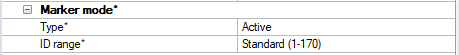
When Type is set to Active or Passive + Active, the setting ID range becomes available. The ID range setting sets the sequence length that is used to define unique blinking patterns that are used to identify the markers. The options are:
-
Standard (1-170)
Standard ID range of 170 uniquely defined markers using a sequence length of 21 frames. This is the default option.
-
Extended (1-740)
Extended ID range of 740 uniquely defined markers using a sequence length of 41 frames. Use this range if you have more than 170 active markers. This option is only supported for the Active and the Naked Traqr in combination with Arqus or Miqus cameras. The Traqr units need to be correctly configured using the Traqr configuration tool.
For information about the use of passive and active markers, see chapter Passive vs Active markers. For information about Qualisys active marker solutions, see chapter Active marker types.
The old type of close range active marker is not supported in QTM 2.5 or later. Please contact Qualisys AB if you use this type of active marker.
Image size
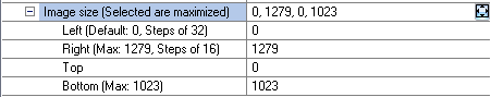
With Image size
it is possible to change the pixels that are active when you capture marker
data. The setting can be set individually for each camera. Use the maximize
button ![]() to reset the selected cameras to the maximum image size.
to reset the selected cameras to the maximum image size.
The image size is specified in Left and Right, Top and Bottom. Where the Left and Right values can only be specified in certain steps depending on the camera type. The steps for the current model is displayed next to the settings. The maximum size depends on the camera type and the selected sensor mode.
By reducing the image size it is possible to increase the capture frequency. The frequency range will be updated automatically when you change the size. The image size is showed with a red rectangle in the preview 2D view window. The cameras will still capture markers outside the rectangle in preview, but when you make a measurement that data is discarded. In the 2D view of a file the aspect ratio of the camera view is adapted to the reduced image size.
The red rectangle representing the image size is not drawn linearized, this means that with wide angle lens it is best to turn off the Show linearized data option on the 2D view settings page to see the true positions of the mask and image size.
Notes on image size for specific camera models:
-
The image size of Arqus, Miqus, 2c, 5+, 6+ and 7+ series cameras is only limited in the y-direction when increasing the capture rate. However when increasing the capture rate on the Camera settings sidebar then the image ratio is kept. You can then increase the width of the image size by dragging on the red rectangle.
-
The 16 extra pixels of the 3+-series are not active pixels and will be displayed as a black band, if you zoom in on the right side of the image.
-
The x size of the 3-serie camera must be at least 160 pixels. The x size of the 3+-serie camera must be at least 144 pixels in Standard mode and 72 pixels in High-speed mode.
-
The image size of the 5-series camera can only be changed in the y-direction. This is because the frame rate on this sensor will not be increased when changing the number of pixels in the x-direction.
Marker masking
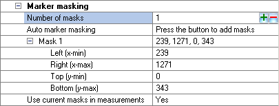
With the Marker masking option, masks can be added to the camera image. The masks will be shown as green areas in the Marker and Marker intensity mode. Any detected markers within the masked areas are discarded from the camera output. For information on how to use the marker masking, see chapter How to use marker masking.
Use the ![]() button on the Auto
marker masking option to automatically add markers masks to the
selected cameras. You can select several cameras when applying the auto
marker mask, but it is important to remove any real markers from the volume.
The cameras must be in RT/Preview mode to use this feature. For more information,
see chapter How to use auto marker masking.
button on the Auto
marker masking option to automatically add markers masks to the
selected cameras. You can select several cameras when applying the auto
marker mask, but it is important to remove any real markers from the volume.
The cameras must be in RT/Preview mode to use this feature. For more information,
see chapter How to use auto marker masking.
The marker mask is set individually for each camera.
Select one camera and add a mask by clicking the plus button ![]() on the Number of masks line. The maximum number of masks per camera is 20 for Arqus and Miqus cameras and 5 for Oqus cameras. Use the minus button
on the Number of masks line. The maximum number of masks per camera is 20 for Arqus and Miqus cameras and 5 for Oqus cameras. Use the minus button ![]() on the line to remove a mask. Modify the values for the mask in the list.
on the line to remove a mask. Modify the values for the mask in the list.
-
Left (x-min)
The start pixel of the masking area in X-direction in camera coordinates.
-
Right (x-max)
The end pixel of the masking area in X-direction in camera coordinates.
-
Top (y-min)
The start pixel of the masking area in Y-direction in camera coordinates.
-
Bottom (y-max)
The end pixel of the masking area in X-direction in camera coordinates.
-
Use current masks in measurements
Enable the use of the marker masks in the measurements. Use this option to turn off the masks to check that the masks are correct. The masks will be grey in the Marker and Marker intensity mode and you can see the markers behind the mask.
Notes on masks:
-
Masks are applied on-camera, which means that masked markers are not recorded in QTM and cannot be restored. If you need to apply masks to a file, you can use software masks instead, see chapter How to use software marker masks.
-
The origin of the camera coordinates is the upper left corner of the 2D view and X-direction is horizontal and Y-direction is vertical.
-
The pixels can be converted to subpixels by a multiplication of 64.
-
Marker masks are not drawn linearized, this means that with wide angle lens it is best to turn off the Show linearized data option on the 2D view settings page to see the true positions of the mask and image size.
Marker circularity filtering (Oqus)
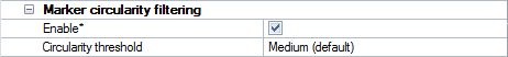
For Oqus cameras the option to use marker circularity filtering is available. The Marker circularity filtering options are used to filter non-circular markers in the 2D data. The default is that the filtering is not Enabled. For more information about the filtering see chapter Marker circularity filtering (Oqus only).
The marker filtering is done in the camera according to the options below.
-
Enabled
To turn on the filtering check the Enabled checkbox. Which markers that are filtered out depends on the Circularity level option.
-
Circularity level
The Circularity level option defines which markers are filtered out as too non-circular. These markers are then processed according to the Non-circularity marker settings on the 2D preprocessing and filtering page.
The option has five levels: All markers, Low, Medium, High and Very high. The default value is Medium. When set to All markers, then all markers are considered to be non-circular and all segments are therefore, if possible, sent to QTM. The levels Low to Very high corresponds to a circularity relation of 20 to 80% between x- and y-size.
There can be too many markers considered as non-circular in the camera. In that case there is a red warning in the left upper corner of the 2D view and all the markers that the camera has not been able to process are considered to be OK.
Marker limits
The Marker limits settings decides which reflections that are detected as markers by the cameras. When Use default settings is set to True no marker limits are used and QTM will detect all reflections as markers.
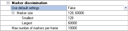
Set the Use default settings to False to set other Marker limits settings. The setting can be set individually for each camera. The Marker limits settings are applied on-camera, which means that discarded markers are not recorded in QTM and cannot be restored.
There are three discrimination settings:
-
Marker size
-
Smallest
The Smallest parameter controls the smallest detectable size of a marker (in subpixels) for each camera in every frame. Any marker smaller than this will be discarded from the camera output.
This option might be useful to screen out tiny non-marker reflections or to assure a minimum size of the markers seen by the camera.
The minimum value of this parameter is 128 and the maximum is the value of the Largest parameter.
-
Largest
The Largest parameter controls the largest detectable size of a marker (in subpixels) for each camera in every frame. Any marker larger than this will be discarded from the camera output.
This option might be useful to screen out reflections of other cameras, which tend to be large. It is also useful on other large non-marker reflections.
The minimum value of this parameter is the value of the Smallest parameter and the maximum is 60000.
The Smallest and Largest parameters are expressed in subpixels, i.e. the sizes depend on the distance between marker and camera. Check the 2D data in the Data info window to see the size of the markers you want to remove.
-
-
Max number of markers per frame
The Max number of markers per frame parameter controls the maximum number of markers transmitted by each camera on a per frame basis. The value can be specified with any integer between 1 and 10000.
When there are more markers in a frame than the value of this parameter, some will be skipped. Since markers are calculated from the top of the image and downward, markers will be skipped from the bottom of the camera’s FOV. For example, if there are 10 real markers within the FOV of a camera and the Max number of markers per frame parameter has been set to 5 markers, it is just the 5 topmost markers that will be calculated and transmitted to the measurement computer.
Exposure delay
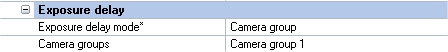
The Exposure delay setting shifts the exposure of a camera compared to other cameras in the system. This can be used when the flash of a camera disturbs another camera in the system. However, because the time of the exposure will be different in the camera system the 2D position that corresponds to the first exposure group is predicted by the 3D tracker. The prediction of the 2D position works best when using a higher frame rate. For more information see chapter Delayed exposure to reduce reflections from other cameras.
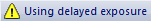
To activate the exposure delay, select Camera group or Advanced on the Exposure delay mode setting. When the delayed exposure is activated Using delayed exposure is displayed in the Status bar. The delayed exposure setting is displayed in each camera's 2D view, e.g. expgrp: 1 when the camera is in exposure group 1.
The recommended mode is Camera group because then the delay is calculated automatically. First select the cameras that you want in the group from the camera list to the left. Then select one of the five groups in the Camera groups setting. E.g. if you only have two groups you should use group 1 and 2. QTM will then automatically delay the exposure time of the groups so that the delay for a group is the same as the longest exposure time in the group before. This means that you can use any exposure time for the cameras and the delay will always be correct.
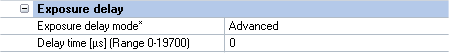
The Advanced mode should only be used if you are completely sure about what you are doing. The delay is then set with an absolute time in the Delay time setting. The delay time will be the same even if you change the exposure time of a camera in the system, which means that you must then manually change the Delay time for the cameras to keep the correct delays to reduce reflections.
Notes on exposure delay for specific camera models:
-
The Arqus A5 camera is more sensitive to light outside of the exposure time, compared to other Arqus cameras. It means that the exposure delay can remove reflections from other cameras, but you usually need to use marker masks to remove direct light from other cameras.
-
Delayed exposure does not work for the Oqus 5-series camera.
Sensor mode

The Sensor mode option can be used to reduce the resolution to get a higher capture ratewhile keeping the same field of view. The option is only available for camera models that have more than one sensor mode. The setting can be changed individually on each camera and also for Marker and Video mode separately. The sensor mode setting can also be changed on the Camera settings sidebar. For an overview of available sensor modes per camera model, see Qualisys camera sensor specifications (marker mode).