Processing 2D data
The 2D data is processed when the Pre-process 2D data option is enabled on the Processing page in Project Options. When reprocessing 2D data in a file, the 3D, 6DOF and skeleton data must also be reprocessed for the changes to have any effect.
The following pre-processing and filtering methods for 2D data are available:
-
Circularity filter (a legacy filtering method, only supported by Oqus cameras)
-
Software marker masks
-
Marker size filter
How to use circularity filter (Oqus only)
The circularity filter can be used to correct or delete bad or partially hidden markers. It is only available when the Marker circularity filtering option is enabled for the camera, see chapter Marker circularity filtering (Oqus only).
The quality of 3D data and how to use the filter depends a lot on the number of cameras in the system. If you have three or more cameras covering the same markers, it is usually better to try to remove the non-circular markers. Because then you have enough data to create the 3D data anyway. However, if there is usually just two cameras viewing the same markers the data can become more complete by correcting the non-circular markers. This will result in more 3D data, which otherwise cannot be calculated.
The filter has two options: Correct center point of non-circular markers and Discard non-circular markers.. One of the options must be selected for the 2D preprocessing. Use the following advice to set the settings for the different options.
-
Correct center point of non-circular markers
Any markers that have been filtered out by the camera as non-circular will be fitted to a circle if possible and merged markers are also corrected.
-
Circularity level
In this mode you can set the Circularity level, in the camera settings, depending on how many markers you have. Try to find a level where the camera has time to process the markers.
-
Effect on 3D data
This mode will give you more exact 3D data than the unfiltered data, because the corrected markers have more exact center points than the camera data. It has most effect if only two cameras can see the marker. For example you can use this mode to improve the accuracy of the calibration, since the wand markers are partially hidden by the stick.
Corrected merged markers are always used by the 3D tracker. Uncorrected non-circular markers will not be used by the 3D tracker if two other cameras with circular markers can see the marker.
-
-
Discard non-circular markers
All markers that have been detected as non-circular by the camera are removed from the 3D tracker.
-
Circularity level
Check the dark yellow markers in the 2D data to find out which markers are not used by the 3D tracker. Then set the level, in the camera settings, according to how much you want to delete.
-
Effect on 3D data
This mode will give you less 2D data than the unfiltered data and actually most of the time it is better to try to correct the markers. The biggest advantage with this mode is that it is faster than correcting the markers. So if you have many cameras that can see each marker you will not loose much 3D data and it will also be more exact.
-
If you change this option when processing a file, you must also reprocess the 3D, 6DOF and skeleton data for the change to have any effect.
How to use software marker masks
The software marker masks can be used to remove markers in specific areas of recorded 2D data. Software masks can be useful to discard unwanted markers that are contained in a limited area throughout the measurement.
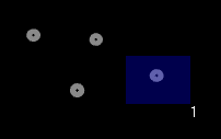
Adding and applying software masks
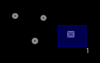
Add software marker masks to a file with the Marker mask tool in the 2D view. The mask is shown as a blue rectangular area. Use the Selection tool in the 2D view to resize and move the mask with the pointer. There can be up to 100 masks per camera. Software marker masks are drawn linearized, so it is best to keep the Show linearized data option enabled on the 2D view settings page.
To apply the software masks, the QTM file must be reprocessed with the Pre-process 2D data step and the Software marker mask option enabled. After processing, the masks are surrounded by blue edges, indicating that they have been applied. The markers that are filtered are surrounded by white rectangles.
The 3D, 6DOF and skeleton data must also be reprocessed for the change to have any effect.
Undoing and removing software masks
To undo the filtering by software masks, the QTM file must be reprocessed with the Pre-process 2D data step enabled and the Software marker mask option disabled. The masks will be preserved, but the filtering is undone. The masks are shown as blue rectangular areas without the surrounding edge, the same as when they were just created.
To delete masks, right-click on a mask and select one of the available options:
-
Delete this mask to delete the currently selected mask,
-
Delete all masks to delete all masks for the current camera,
-
Delete all masks for all cameras to delete all masks for all cameras.
If the masks were applied before deleting, the markers are still filtered, as shown by the white rectangles and the remaining blue edges indicating the masked areas.
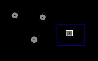
To undo the filtering, the file must be reprocessed with the Pre-process 2D data step enabled (the Software marker mask option can be either enabled or disabled).
The 3D, 6DOF and skeleton data must also be reprocessed for the change to have any effect.
How to use marker size filter
The 2D data can be filtered on the size of the markers. Set the minimum and/or maximum size in subpixels for the markers in the file with the options: Minimum marker size and Maximum marker size.
To apply the marker size filter, the file must be reprocessed with the Pre-process 2D data step enabled, and one or both of the Minimum marker size and Maximum marker size options enabled. When a marker is discarded by the filter, it is displayed with a white square in the 2D view, and the 2D data is not shown in the Data info window.

To undo the size filtering, reprocess the file with the Pre-process 2D data step enabled and the Minimum marker size and Maximum marker size options disabled.
If the marker size filter is changed when processing a file, the 3D, 6DOF and skeleton data must also be reprocessed for the change to have any effect.