Setting up the analog board
The analog board is activated on the Input Devices page in the Project options dialog, see chapter Input Devices. The analog board settings are saved in the project with the serial number of the board. So after an analog board has been used in a project then it is visible even if you disconnect the board from the computer or it is not active in Instacal.
It is important to activate channels, where a cable is connected,
on the page for the active analog board in the Project options
dialog. It is also a good idea to not use the channels where nothing is
connected, since these channels will only make the file larger.
The number of analog samples (frames) depends on the Sample rate setting on the page of the analog board in the Project options dialog, see chapter Sample rate. The number of analog frames, therefore, does not have to be the same as the number of frames in the marker capture.
Another setting on the page for the analog board in the Project options dialog is the remove offset and drift option. Offset is for example that a force plate has an output that differs from 0 V when it is unloaded. Drift is for example when the output from the force plate slowly changes even when it is unloaded. There is a warning in QTM if the offset value is higher than 5 V, see chapter Analog offset warning.
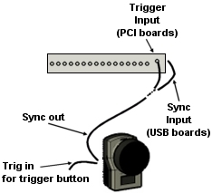
To get synchronized analog data and motion capture data, a synchronization signal must be connected to the analog board through a BNC cable.
-
If you have a Camera Sync Unit, use the OUT1 or OUT2 port.
-
If you have an Oqus system, connect a BNC sync/trig splitter to the control port of the camera to be used a the synchronization source and use the Sync out connector.
For Oqus it is recommended to connect the sync cable to the Master camera if the synchronization signal is faster than 5000 Hz.
The recommended synchronization option is the frame synchronization. To use this synchronization option:
-
Select the External sync (frame sync) option for the analog board, see chapter Sample rate.
-
Connect the synchronization cable to the Sync connection on the back of the analog board.
For USB-2533 the trigger edge that is used by the board can be set in Instacal see chapter Installing the USB-2533 board. Make sure that the XAPCR edge setting for the board matches the TTL signal polarity setting on the Synchronization page in the Project options dialog.
The other option is to simultaneously start the analog capture with the camera system. To use this synchronization option:
-
Select the Simultaneous start option for the analog board, see chapter Sample rate.
-
Connect the synchronization cable to the External trigger or Trig connection on the A/D board.