Connecting an Arqus system
An Arqus system consists of the following components:
-
Arqus cameras
Arqus cameras of one or several types. -
Camera cables
The number of camera cables is the same as the number of cameras. -
One or more Power kits
A power kit consists of a power supply, a power injector and a host (Ethernet) cable. One power kit can power up to 5 Arqus cameras. -
Camera Sync Unit (optional)
A Camera Sync Unit is required for synchronization with external equipment. -
Gigabit Ethernet switch (optional)
The use of a switch is required for systems with more than 20 Arqus cameras.
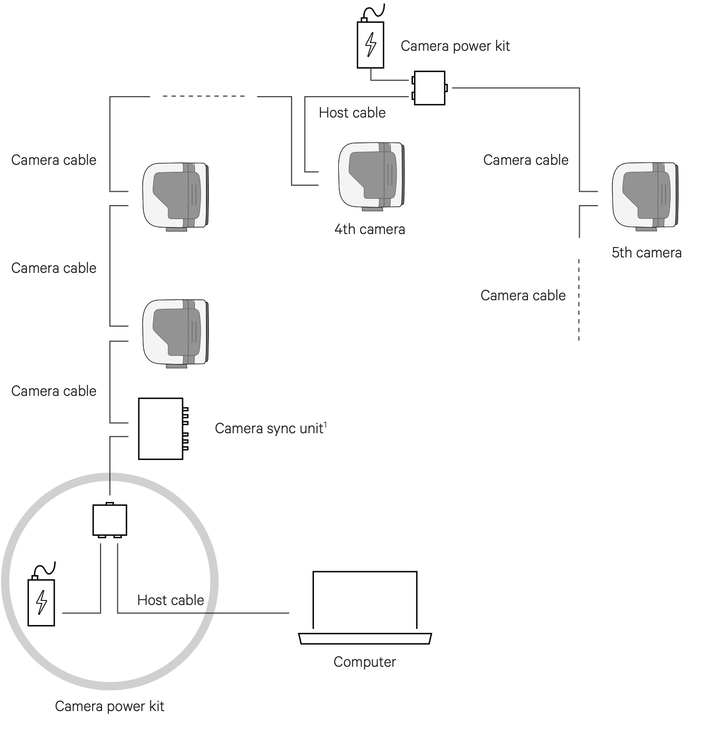
The Arqus system is easy to connect. The backside of each camera contains two Data/Power ports, see chapter Arqus camera: back side. In a basic setup with up to 5 cameras, the cameras are connected to each other by camera cables in a daisy chain configuration. For the maximum number of cameras and the maximum cable length per power supply, see chapter Power and camera cable requirements.
The first camera or Camera Sync Unit is connected via a Power injector to the power supply and the computer as follows:
-
Connect the power supply to the Power port on the power injector.
-
Connect one end of the host cable to the to the Data port on the power injector and the other end to the Ethernet port of the computer.
-
Connect one end of the camera cable to the Camera port on the power injector and the other end to a Power/Data port of the first camera or the Camera Sync Unit.
For larger systems, start a new power chain when the maximum of 5 cameras per power chain is reached. Connect the first camera of the new power chain (camera 6, 11, 16) via a Power injector as follows:
-
Connect the power supply to the Power port on the power injector.
-
Connect one end of the host cable to the to the Data port on the power injector and the other end to a Power/Data connector of the previous camera.
-
Connect one end of the camera cable to the Camera port on the power injector and the other end to a Power/Data connector of the first camera in the next power chain.
For systems with more than 20 cameras, the use of a switch is required. The system can then be subdivided in chains with up to 20 cameras. The chains are connected with their respective host cables to a switch, which in its turn is connected to the computer.
The Camera Sync Unit can be placed anywhere in the chain, but in most cases it will be practical to have it close to the computer.
When the cables have been connected correctly, the indicator LEDs at the Arqus data/power ports will indicate the status of the power and data connection. For more information, see chapter Arqus camera: back side.
The Arqus startup sequence
Before you connect the Arqus camera system, make sure that the QDS (Qualisys DHCP server) is running and that the network interface settings are correct. This is needed for the cameras to receive an IP address from QDS to communicate with other Qualisys cameras and the host computer. For more information, see QDS and Network card setup.
The general Arqus startup sequence is as follows (total duration about 50 s):
-
Connect the power to the cameras.
-
Booting of the cameras. The amber LED ring is lit during booting.
-
The camera receives an IP address.
If the camera does not receive an IP address the amber LED ring pulses. Possible reasons for this might be that the system is not connected to the computer, or that QDS is not running. For instructions on how search for the error, refer to chapter Troubleshooting connection.
-
The cameras synchronize to the master camera. The status LED blinks green during synchronization. When synchronization is completed it lights solid green.
Setting aperture and focus
The Arqus A12 with standard lens option has a motorized lens, which can be controlled from QTM via the Lens Control interface in the Camera Settings sidebar in the 2D View window, see Camera settings sidebar.
When using motorized lenses, it is important to keep some space between the strobe and the lens, otherwise the strobe may block the lens when changing focus.
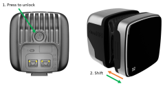
For Arqus cameras with a manual lens, you need to extend the strobe mechanics to get access to the focus and aperture rings of the lens. The strobe mechanics can be shifted as follows:
-
Press and hold the Strobe unlock button at the backside of the Arqus camera.
-
Shift the strobe mechanics outwards to expose the lens for adjustment.
-
Shift the strobe mechanics inwards again when done. You may have to fine adjust the position of the strobe mechanics so that it locks into the dimples on the strobe rails.

The strobe should always be in closed position during measurement to achieve the best strobe light distribution, and to make sure that the strobe does not block the peripheral view of the lens.
For general recommendations on settings aperture and focus, see chapter Tips on setting aperture and focus.