Trajectories in 3D views
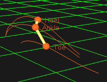
The trajectories of a measurement are shown with markers on their current position in the 3D view, where the colors of the trajectories are the same as in the Trajectory info windows.
In File mode, the position throughout the measurement can be displayed with a trace, where the length of the traces is controlled by the bottom sliders on the Timeline control bar. The trace of a trajectory is thicker when the focus is set on its trajectory in the Trajectory window, i.e. there is a dashed box around it.
You can change settings for the marker and trace display on the 3D view settings page in the Project options dialog. Among other things you can turn on the display of the marker labels.
The trajectories can either be created with 3D or 2D tracking, but the display in the 3D view window is the same except that 2D tracked trajectories are displayed in a plane. The data of the marker is shown in a Trajectory info window, see chapter Trajectory info windows.
The following actions can be performed with the Selection cursor on a trajectory in the 3D view.
-
Select
Click on the marker or the trace of the trajectory to select it. Use the following keys to modify the action when you click on a trajectory.
-
Hold down Alt to only select a part of the trajectory.
-
Use Shift and Ctrl to add and delete (only Ctrl) trajectories to the selection.
-
Hold down Shift and drag the mouse to use area selection.
-
-
Drag and drop for identification of trajectories
Trajectories can be drag-and-dropped from the 3D view to labeled trajectories to change their identity. For example, drop an unidentified trajectory from the 3D view onto an empty label in the Labeled trajectories window to identify it. In case the labeled trajectory is not empty, this requires that there is no overlap between the trajectories.
A trajectory can also be dropped on the trace of another trajectory in the 3D view to join them. This can be used in combination with scrubbing (hold down Control and drag the mouse in empty 3D space) and trace range zooming (hold down Shift and roll the mouse wheel).
When using skeletons, the trajectories can be dropped on available (red) segment markers to label them.
The file must be reprocessed to update the 6DOF or Skeleton data.
-
Trajectory info window menu
Right-click on a trajectory to open the Trajectory info window menu for the selected trajectories, see chapter Trajectory info window menu.
-
Information
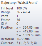
Place the cursor over a marker or a trace to see a tool-tip with information about the trajectory.
-

-
Delete
Use the Delete key to delete selected trajectories and parts of trajectories directly in the 3D view window.
Trajectories in the Discarded trajectories window are hidden by default.
-
Quick identification
The quick identification method provides an easy way to manually identify the markers. First select an empty label. Then hold down Ctrl + Alt or select the Quick identification cursor to activate this method. Then click on a marker and it will be identified as the currently selected empty label in the Labeled trajectories window. For more information about quick identification, see section Manual identification of trajectories.
-
Create bones
To create a bone, hold down Shift and select a pair of labeled trajectories by clicking in the 3D view window. Then press B and there will be bone between the pair. Several bones can be created with the Create bones sequence tool.
-
Center on trajectory
Select a trajectory and press C to change the viewpoint so that it centers on that marker. You can also use the Center trajectory cursor and click on the marker.