3D view settings
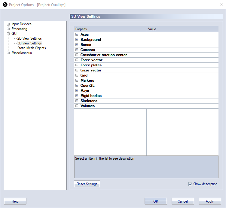
The 3D view settings page contains settings for objects that is shown in the 3D view window and also how to operate the 3D view. The settings are saved with the project and are applied both in the RT/preview and on a opened file.
You can use the Reset settings button if you want to reset all of the settings to default. Only the more complex settings are explained below, for explanation of the other settings please check the description in the Project options dialog.
The display of some of the 3D view elements can be changed directly on the GUI Control toolbar.
-
Axes
Display settings for the global axes in the 3D view.
-
Show axes, Length of the axis [mm]
-
-
Background
Display setting for the background in the 3D view.
-
Background color
-
-
Bones
Display settings for the bones in the 3D view.
-
Show bones, Show AIM structure bones, Bone thickness [mm], Bone default color
The Show AIM structure bones option toggles the display of the AIM structure bones used to create an AIM model.
-
-
Cameras
Display settings for the cameras in the 3D view.
-
Show cameras, Show camera IDs
-
-
Crosshair at rotation center
Display settings for the crosshair shown when zooming and translating in the 3D view.
-
Show crosshair, Crosshair color, Crosshair size [pixels]
-
-
Force vector
Display settings for the force vector in the 3D view.
-
Show force vector, Force vector color, Scale factor [mm/N], Show force trace
The Scale factor option sets the size of the force arrow in relation to the force in N.
Activate the force trace, also called force butterfly or Pedotti diagram, with the Show force trace option. The force trace is shown for the active measurement range.
-
-
Force plates
Display settings for the force plate in the 3D view.
-
Show force plates, Force plate color,
-
-
Gaze vector
Display settings for the Gaze vector of eye-trackers.
-
Show gaze vector, Gaze vector color, Gaze vector length [mm], Show gaze vector trace and Gaze vector trace color.
-
-
Grid
Display settings for the grid in the 3D view.
-
Show grid, Show grid measure, Grid color, Automatic size, Grid length [m], Grid width [m], Vertical offset [mm], Distance between each gridline [mm], Number of subdivisions, Thicker lines on outside and center
The Automatic size option will make the grid approximately the same size as the lab area, i.e. the size is set by the camera positions.
-
-
Markers
Display settings for the markers in the 3D view.
-
Default unidentified marker color, Default labeled marker color, Use global marker size setting, Marker size (mm), Show marker labels, Show marker traces, Traces line style, Show trajectory count, Show labeled trajectory information, Show unidentified markers
The Use global marker size setting option will decide whether to use the same marker size on all files or individual settings for each file. Disable the option to use the marker size that was used when a file was saved.
The Show trajectory count option will display the number of selected trajectories and the total number of trajectories in the current frame at the bottom right corner of the 3D view window.
The Show labeled trajectory information option shows the status of the labeling at the current frame in the upper right corner of the 3D view window.
-
-
OpenGL
-
OpenGL format selection mode
The default values will give the best quality of graphics. However if there are any problems with the graphics first try to disable the anti-aliasing, then try one of the other modes: Use options below or Use explicit index.
-
Use full scene anti-aliasing if available
Anti-aliasing smooths the edges of the graphics, but it can also slow down the playback. This feature is not available on graphic boards where the driver doesn't support OpenGL 2.0.
-
OpenGL double-buffering (only available for Use options Below)
The default setting is to Use double buffering. But to reduce the workload on the graphic board you can try Use front buffer only or Use single buffer only.
-
Use HW acceleration (only available for Use options Below)
Disable the acceleration if the graphic board has no built-in memory.
-
OpenGL format number (only avialable for Use explicit index)
Set the index for the OpenGL format, however some indexes might not work at all. To see a list of the available formats click on the
 button.
-
-
Rays
Display settings for camera tracking rays in the 3D view.
-
Enable camera rays
Show/hide camera rays
-
Length of ray excess [mm]
Additional length of ray beyond the calculated intersection point.
-
-
Rigid bodies
Display settings for the rigid bodies in the 3D view.
-
Show rigid bodies, Show coordinate system axes, Length of the coordinate system axes [mm], Show rigid body points as markers, Show rigid body labels, Show rigid body wireframe, Show rigid body mesh
Activate the display of the rigid body points in the 6DOF definition, with the Show rigid body points as markers option. The markers are calculated from the 6DOF definition and therefore they will be displayed even if the corresponding marker is hidden.
-
-
Skeletons
Display settings for skeletons in the 3D view.
-
Show skeletons, Show skeleton labels, Skeleton color, Skeleton thickness, Show segment labels, Show segment coordination axes, Show segment markers, Show segment constraints, Constraint tolerance range [%], Segment constraint color
-
-
Static mesh objects
Display settings for static mesh objects in the 3D view.
-
Show static mesh objects
-
-
Volumes
Display settings for the display of volumes in the 3D view, for more information see chapter Volumes in 3D views and Camera view cones in 3D views.
-
Show covered volume, Cut covered volume at floor level, Cameras required to consider volume covered, Show calibrated volume, Enable camera view cones, Length of camera view cones [m], Show bounding box
-