Arsalis
The Arsalis device settings are managed via the Arsalis settings page. Once the Arsalis force plates are set up correctly, the force calculation can be defined under the force plate settings, see chapter Force plate settings.
For information about how to connect and set up Arsalis force plates for use with QTM, see chapter Connecting Arsalis force plates.
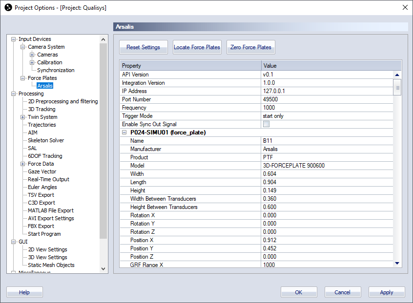
The Arsalis page contains three buttons to communicate with the force plates and a list with settings for the located force plates.
-
Reset Settings
Reset settings all of the Common settings to their default values. -
Locate Force Plates
Locate the force plates that are currently activated in the 3D-Forceplate software. -
Zero Force Plates
Zero the force data for all of the currently connected force plates.
The settings list contains a top section with common settings and a section with individual settings for each force plate.
-
Common settings
The common settings are always visible.-
API version
The API version used when creating the integration. Hover over the version number to compare with the API version used by QTM. -
Integration version
The version number for the integration. -
IP Address
Enter the IP address for the computer running 3D-Forceplate software. -
Port Number
Enter the port number used by the Local server in the 3D-Forceplate software. -
Frequency
Enter the frequency for the force plates. The plates supports the following frequencies: 100, 200, 250, 400, 500, 1000, 2000. Make sure that you select one that can be evenly divided by the camera frame rate. -
Trigger Mode
Set the trigger mode for the force plates. The default value is start only. This is the recommended mode since you then get a synchronized start with the camera system. Note that you must make sure that the trigger options are correct in the 3D-Forceplate software.
The other available options are as follows. The none option doesn't have any hardware synchronization. The stop only option will stop on the signal and the both option will both start and stop on the signal. There is currently no way to configure the sync signal from the cameras in a way that is compatible with the two last options. -
Enable Sync Out Signal
Enable a sync signal on the SyncOut port. The signal is configured in the 3D-Forceplate software.
-
-
Individual settings and information for each force plate
The individual settings are only displayed after locating the force plates. Note that all of these settings are imported from the 3D-Forceplate software and cannot be changed in QTM.-
Name, Manufacturer, Product, Model
Information about the force plate. -
Width, Length, Height, Width Between Transducers, Height Between Transducers
Force plate dimension. -
Rotation X, Rotation Y, Rotation Z, Position X, Position Y, Position Z
Rotation and Position of the force plate. -
GRF Range X, GRF Range Y
Ground reaction force ranges for X and Y. -
Channels
The channels captured from the force plates with their respective unit and frequency. Note that the four last channels are either 1 or 0.-
Force X, Force Y, Force Z (N, frequency)
-
Moment X, Moment Y, Moment Z (Nm, frequency)
-
Trigger (frequency)
-
Aux (frequency)
-
Zero (frequency)
-
Sync (frequency)
-
-