Connecting Arsalis force plates
The Arsalis force plates are digitally integrated in QTM. For further information about the force plates, refer to the manufacturer's documentation.
The sections below describe how to connect the force plates and how to set them up in QTM.
Hardware connections
The hardware is connected in the following ways.
-
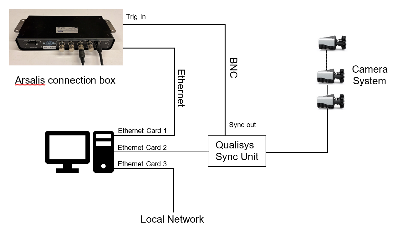
Connection of the force plates
The force plates can be connected to the same computer running QTM or a different computer connected through the same local area network (LAN). Most commonly, the Arsalis connection box is directly connected to a computer via an Ethernet adapter. When connecting to the same computer that is running QTM, make sure that it is not connected to the same physical network as the Qualisys camera system.These instructions describe a setup in which the force plates are connected to the same computer that is running QTM. For detailed instructions on how to connect the force plates and install the 3D-Forceplate software for controlling the force plates, refer to the manufacturer's documentation.
-
Synchronization
The use of hardware synchronization is required and requires a Camera Sync Unit for Arqus or Miqus systems, or a Sync/Trigger splitter for Oqus systems.Connect one of the Sync out outputs of the Camera Sync Unit to the Trig In port of the Arsalis connection box. If you are using an Oqus camera as sync device, use the Sync out connector of the Sync/Trigger splitter. In the Synchronization settings, set the Synchronization output mode for the Sync Out port to Mulitplier with a multiplier of 1. Make sure that the polarity matches between the settings in QTM and 3D-Forceplate. Use the default option of Negative polarity for the sync out signal.
Set up a data stream
Before setting up the connection in QTM, start a data stream in the 3D-Forceplate software.
-
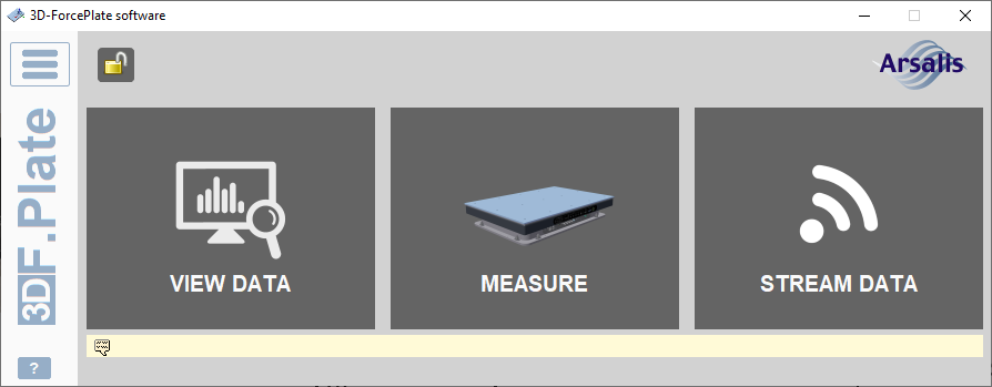
Start the 3D-Forceplate software. If you need to unlock, try the default password 1234.
-
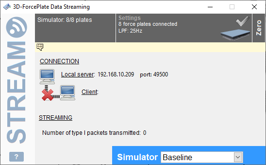
Press Stream data, and zero the force plate. This opens up a 3D-Forceplate Data Streaming window with information about the connection.
If the Stream data option is not available, contact Arsalis support.
-
If running the 3D-Forceplate software on a different computer, make note of the Local server IP address for setting up the connection in QTM.
-
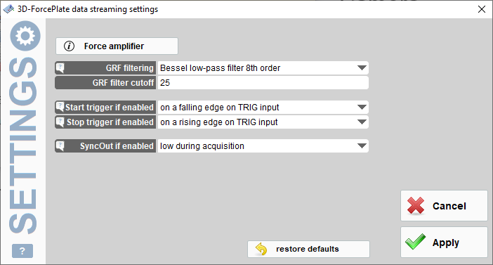
Make sure that the synchronization settings for the data stream are correct. To open the settings dialog, double click on the gray Hardware area in the 3D-Forceplate data streaming window.
Start trigger if enabled should be set to on a falling edge on TRIG input.
Set up and configuration in QTM
Once the 3D-Forceplate data stream is set up, the Arsalis device can be added and configured in QTM.
-
Open the Input Devices page in the QTM Project Options.
-
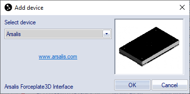
Click the Add Device button, and select Arsalis in the drop down menu.
-
Check the Arsalis item in the Input Devices list. The Arsalis device should now show up as an input device under the Force Plates category.
-
Open the Arsalis settings page, see chapter Arsalis.
-
Fill in the Local server IP address in the IP address setting. If the force plate is connected to the same computer that is running QTM, you can use the localhost IP address (127.0.0.1).
-
Fill in the Port Number of the server. Make sure that it is the same as in the 3D-Forceplate Streaming Window.
-
Press the Locate Force Plates button in QTM. If the connection is established, the information about the Arsalis force plates will show up in the list below.
-
Make sure that the Trigger mode option is set to start only to get synchronized start of the force plates.
-
Finalize configuring the device by setting the sample rate with the Frequency option.
-
You can also zero the force plates from the Arsalis settings page.
When the force plates have been added to QTM, the next step is to configure the force data calculation. The steps below presume that the force plate locations for your setup have already been defined in the 3D-Forceplate software.
-
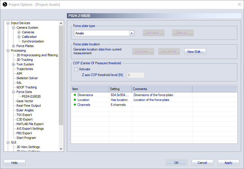
Go to the Force Data page.
-
Click on Define Plates to import the definitions for all the current Arsalis force plates to the Force plates list.
-
Make sure that the plates you want to use are enabled in the list. You do not need to do any other settings for the plates, but you can open the settings for each force plate by double-clicking on it in the list.
-
Make sure that the force plate dimensions are known in the Force plate status settings list. The force plate dimensions are retrieved automatically when connecting the force plates in QTM.
-
You can set the location of the force plate with the View/Edit button, but it is recommended to use the locations that are entered in 3D-Forceplate. This requires that the L-frame for the camera calibration is placed at the origin used to define the locations in 3D-Forceplate.
-
Optionally, activate the COP threshold to suppress the visualization of the force vector in QTM when there is no load on the force plate.
-
Activate the Calculate force data option on the Processing page. To see the force both in preview and in captured files, make sure that it is activated both for Real-time actions and Capture actions.
Capturing, viewing and exporting data
To collect data with the Arsalis force plates, simply start a capture in QTM. The 3D-Forceplate Streaming window should show an active client connection when QTM is in preview and during capture.
To view the Arsalis data during preview or a capture, open a Data Info window via the View menu (keyboard shortcut Ctrl + D), right-click in the window and select Analog data. The Arsalis analog data includes forces, COP, free moment and several other signals. To show the force data calculated by QTM, right-click on the Data Info window and select Force data.
When exporting to C3D, the analog data will be resampled to the closest integer multiple of the capture frequency, or higher depending on all analog data stored in the QTM file, see chapter C3D file format.