Export to MAT format
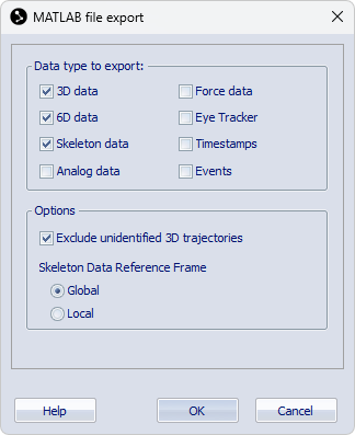
Click Export on the File menu and then To MAT to export to the MAT format. The MAT file can then be opened in Matlab. You can select the data that is exported on the Matlab file export page in the Project options dialog, see chapter Matlab file export.
MAT file format
Capture data is exported to a MAT file as a single structure array (struct) with the same name as the file. In case the file name is not a proper variable name in Matlab, the name of the struct will be altered. For example, if the file name does not start with an English letter, a prefix qtm_ will be added to the name of the structure.
The fields of the structure array contain information and data of the capture. Data in a field is accessed using dot notation of the form structName.fieldName. If a field contains a structure array with multiple elements, a single element is accessed by indexing the field, for example, MyCapture.Skeletons(3).SkeletonName to access the name of the third skeleton. If a field contains a multidimensional array, data points are accessed by indexing the array, for example, MyCapture.Trajectories.Labeled.Data(3,1,134) to access the X value of frame 134 of the third labeled trajectory. For more information about accessing data in Matlab, refer to Matlab documentation.
To read data from a QTM exported MAT file into a struct with a name of your own choice, rather than the file name, copy the following function and make sure it is included in your Matlab path:
function qtm=qtmread(fn)

% Get file name from a file dialog if not specified
if nargin==0
    [fname,pname] = uigetfile({'*.mat', '.mat files'}, 'Load QTM mat file');
    fn = [pname fname];
end

% Load the file
S=load(fn);

% Parse S
sflds=fieldnames(S);
if length(sflds)>1
    error('Only one variable (struct) is expected in a .mat file exported by QTM.')
else
    qtm=S.(sflds{1});
end
To read the exported file into a variable, for example MyVarName, run the function in Matlab:
>> MyVarName = qtmread();
or
>> MyVarName = qtmread(<file path>);
For specific information about the format of the exported structure array, see the chapters below.
Capture information
The following fields contain information about the capture.
-
FileVersion
Version number of export format (array with 3 elements), currently 2, 0, 0.
FileVersion is not included for versions earlier than 2, 0, 0.
-
File
File name and directory path.
-
Timestamp
Time when measurement was started. In date format YYYY-MM-DD, HH:MM:SS.SSS, followed by a tab character and the timestamp in seconds and ticks from when the computer was started.
The time stamp is recalculated when trimming the file.
The time stamps indicate the start of the capture according to the QTM software. The time stamps may not exactly correspond to the first frame of the capture and it is discouraged to use them for synchronization with data from other devices connected to the same or another synchronized computer.
-
StartFrame
The measurement start frame number.
-
Frames
Number of frames.
-
FrameRate
Frame rate in frames per second.
When using external timebase the frequency is set to the actual frequency for the Multiplier/Divisor mode and to EXT for the Edge triggered mode.
Trajectories
The field Trajectories contains the structures Labeled for labeled markers and, optionally Unidentified for unidentified markers with the following fields:
-
Count
Number of trajectories in the window.
-
Labels
A list of the trajectory labels.
This field is only included in the Labeled struct array.
-
Data
The location of the 3D points (in mm) of the trajectories in the window. The data is given in a matrix with the dimensions: Trajectories x X, Y, Z, Residual x Frames.
-
Type
Type specification of the markers per frame. The data is given in a matrix with the dimensions: Trajectories x Frames. The types have values 0-4, which indicate: Missing=0, Measured=1, Gap-filled=2, Virtual=3, Edited=4.
-
TrajectoryType
A list of the type for each trajectory. For information about the trajectory types see chapter Data in Trajectory info windows.
Analog/EMG
The fields Analog or EMG contain struct arrays with data from the analog devices. The analog and EMG
data from integrated wireless EMGs are stored in separate struct arrays,
but the structure is the same.
-
BoardName
The name of the board that was used in the capture.
-
NrOfChannels
The number of channels that were used in the capture.
-
ChannelNumbers
The channel numbers that were used in the capture.
-
Labels
An array with the names of the channels that were used on the analog board.
-
Range
The range of the channels on the analog board.
-
NrOfFrames
The number of exported motion capture data frames.
-
SamplingFactor
The multiplication factor compared with the motion capture frame rate. The SamplingFactor is specified per channel in a 1 x NrOfChannels array.
-
NrOfSamples
The number of exported analog samples per channel (1 x NrOfChannels array).
-
Frequency
The sampling frequency of the analog data per channel (1 x NrOfChannels array).
-
Data
Analog data per channel. The data is formatted as a matrix with the dimensions NrOfChannels x max(NrOfSamples). In case the channels have different frequencies, the shorter rows are appended with NaNs.
For analog boards, the units of the exported data are in V. EMG data from integrated devices are exported in μV or mV, depending on the units provided by the device. For other data types from integrated devices, the units are converted to SI units associated with the data type.
Force
The field Force contains a struct array with data from the force plates. The elements of the struct array contain the data per force plate.
-
ForcePlateName
The name of the force plate that was used in the capture.
-
NrOfFrames
The number of channels that were used in the capture.
-
SamplingFactor
The multiplication factor compared with the motion capture frame rate.
-
NrOfSamples
The number of samples in the analog capture.
-
Frequency
The frequency of the analog capture.
-
Force
The force data in newton (N), the data is given for X, Y and Z direction.
-
Moment
The moment data in newton meter (Nm), the data is given for X, Y and Z direction.
-
COP
The centre of pressure on the force plate (in mm), the data is given X, Y and Z direction.
-
ForcePlateLocation
The location of the force plate in measurement coordinate system. The corners are in the order upper left, upper right, lower right and lower left seen in the force plate coordinate system.
-
ForcePlateOrientation
Coordinate system in which force data is expressed: 0 (local force plate coordinates), 1 (global coordinate system).
-
ForcePlateOffset
The force plate offset values as filled in for the specific force plate. The order is the same as on each respective force plate calibration settings in Project options.
RigidBodies
The field RigidBodies contains a struct with data for the 6DOF bodies. The struct contains the data of all rigid bodies present in the file.
-
Bodies
The number of 6DOF bodies.
-
Name
The names of the 6DOF bodies.
-
Filter
Struct array with information about the filter used for the respective rigid bodies.
-
Preset
Name of the filter preset used for the rigid body.
-
-
CoordinateSystem
Struct array with information about the reference coordinate system used for the respective rigid bodies.
-
Reference
Coordinate system option used for the rigid body. The possible options are Global, Relative and Fixed.
-
ParentRigidBody
The number of the reference rigid body used for the Relative coordinate system option. For the Global and Fixed options the number is set to zero.
-
DataOrigin
The fixed origin (x,y,z) used for the Fixed coordinate system option. For the Global and Relative options the value is set to (0,0,0).
-
DataRotation
The fixed rotation matrix in relation to the global coordinate system used for the Fixed coordinate system option. For the Global and Relative options the value is set to the unit matrix.
-
-
Positions
The position of the origin of the measured rigid body’s local coordinate system. It is given as a matrix with the dimensions: Bodies x Coordinates (X, Y and Z) x Frames. The positions are expressed in mm relative to the origin of the used coordinate system.
-
Rotations
The rotation matrices of the rigid bodies. It is given as a matrix with the dimensions: Bodies x Rotation matrix elements (0-8) x Frames. The elements are placed in the matrix according to the following table:
[0]
[3]
[6]
[1]
[4]
[7]
[2]
[5]
[8]
For information about the rotation matrix, see Rotation angle calculations in QTM.
-
RPYs
The roll, pitch and yaw of each rigid body. It is given as a matrix with the dimensions: Bodies x Rotation angles (roll, pitch and yaw) x Frames. The rotation angles are in degrees.
The matrix will always be called RPYs even if the definitions are changed on the Euler angles page in the Project options menu.
-
Residuals
The residual of the rigid bodies.
Skeletons
The field Skeletons contains a struct array with data of the skeletons. The elements of the struct array contain the data per skeleton.
-
SkeletonName
The name of the skeleton [char array].
-
Solver
The type of solver used for the skeleton.
-
Scale
The scale setting used for the skeleton. In the MAT export the scale factor is defined as the inverse ratio. For example, a Scale value of 0.8 corresponds to a scale factor of 125% in QTM.
-
Reference
Reference used for the skeleton data. Global: all segment positions and rotations are expressed relative to the global coordinate system. Local: all segment positions and rotations except the Hips segment are relative to their respective parent segment.
-
NrOfSegments
Number of segments of the skeleton [double].
-
SegmentLabels
Names of the segments of the skeleton [1 x NrOfSegments cell array with char elements].
-
PositionData
Position data (X, Y, Z) of the segments of the skeleton [3 x NrOfSegments x Frames double].
-
RotationData
Segment rotation data in global coordinate system expressed as quaternions (QX, QY, QZ, QW) [4 x NrOfSegments x Frames double].
SMPTETimecode
The field SMPTETimecode contains a struct array with the SMPTE timestamps of the frames in the
file. The elements of the struct array contain the timestamp data per frame.
-
Hour
The hour of the timestamp.
-
Minute
The minute of the timestamp.
-
Second
The second of the timestamp.
-
Frame
The SMPTE frame number of the timestamp.
-
Missing
Indicates if the SMPTE timecode is extrapolated if the SMPTE synchronization source is lost during the measurement.
In QTM versions 2.15 and earlier an additional field Subframe is included, representing an index of marker frames within a SMPTE frame.
The values are represented as int64 numbers in Matlab. To use them in calculations, you may have to convert them to double precision using the
double()function.
IRIGTimecode
The field IRIGTimecode contains a struct array with the IRIG timestamps of the frames in the file. The elements of the struct array contain the timestamp data per frame.
-
Year
The year of the timestamp.
-
Day
The day of the timestamp.
-
Hour
The hour of the timestamp.
-
Minute
The minute of the timestamp.
-
Second
The second of the timestamp.
-
Tenth
The decisecond of the timestamp.
-
Missing
Indicates if the timecode is extrapolated if the IRIG synchronization source is lost during the measurement.
The values are represented as int64 numbers in Matlab. To use them in calculations, you may have to convert them to double precision using the
double()function.
CameraTimecode
The field CameraTimecode contains a struct array with the camera timestamps of the frames in the file. For more information about Camera time, see chapter Timestamp.
The CameraTimecode struct array is only available when the Camera time option is enabled during the capture.
The elements of the struct array contain the timestamp data per frame.
-
Tick
Tick value of camera timestamp. This value represents the time in seconds multiplied with a factor 107.
-
Missing
Indicates if the timecode is extrapolated if the synchronization source is lost during the measurement.
The values are represented as int64 numbers in Matlab. To use them in calculations, you may have to convert them to double precision using the
double()function.
Events
The field Events contains a struct array with a list of all the events in the file. The elements of the struct array contain the data per event.
-
Label
The label of the event.
-
Frame
The corresponding frame of the event. The time will be rounded to the nearest frame.
-
Time
The time of the event.
GazeVector
The field GazeVector contains a struct array with the gaze vector data included in the capture. The elements of the struct array contain the gaze vector data per eye.
-
GazeVectorName
The name of the gaze vector.
-
NrOfSamples
The number of samples in the gaze vector data.
-
StartOffset
The offset time for the first gaze vector frame. It is needed since you may not always cut the measurement range at the start of gaze vector frame. Reduce the start time of the gaze vector data with the offset so that it actually starts before the marker data.
-
Frequency
The frequency of the gaze vector data.
-
HWSync
Indicates if hardware sync was used for the eye tracker data or not. The values can be 0 (no hardware sync) or 1 (hardware sync).
-
Filter
Indicates if the gaze vector data was filtered or not. The values can be 0 (not filtered) or 1 (filtered).
-
GazeVector
Array with the gaze vector data in the following order: X Pos, Y Pos, Z Pos, X Vec, Y Vec, Z Vec. The X/Y/Z Pos values represent the origin of the gaze vector in mm, and the X/Y/Z Vec values represent the 3-dimensional normalized gaze vector.