Linearization procedure and instructions
Linearization concept
The linearization procedure is designed to collect data with the linearization plate in a variety of orientations across the image sensor of the camera. The data is collected based on the following criteria:
- The 2D image is divided into 7 times 6 squares.
- Each square is divided into four orientation cells, visualized as triangles.
- Each orientation cell requires at least 20 valid observations of the linearization plate within the required pose constraints.
- The angle of the plate to the plane of the sensor must be at least 10 degrees to be accepted as a valid orientation.
- The size of the markers must be at least 200 subpixels.
The data for the calculations is automatically selected based on these criteria. The user is guided by the feedback provided by QTM to facilitate the data collection.
Feedback during the linearization procedure
QTM provides the following feedback to guide the user during the linearization procedure:
-
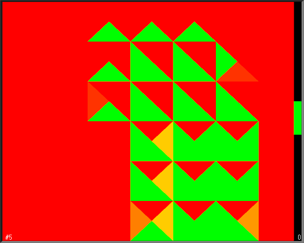
At the start of the linearization, the 2D view turns red. The image is mirrored to make it easier for the user to the move the plate across the area.
-
The markers of the plate are colored when the plate is identified.
-
If the markers are white, it may help to shortly hide the plate from the camera and show it again.
-
If QTM has difficulties to identify the plate, make sure to remove any extra reflections and redo the linearization.
-
-
The distance interval is indicated by the green vertical bar to the right of the 2D view. A white diamond shows the current distance of the plate to the camera, which should be within the green area.
-
When you are too far or too close to the camera, a large white arrow head in the center of the image area shows you if you need to move farther or closer.
-
-
During the data collection, the triangular orientation cells change color as they are filled with valid observations, from red to orange to yellow to green. A green cell indicates that a sufficient amount of data has been collected for that pose.
-
A white line pointing outwards from the center represents the current orientation of the plate.
-
If you need more observations for a triangle, point the plate towards the triangle to collect data for that orientation.
-
-
When the markers are too small, the error Too small markers are shown at the bottom left corner. In this case, try to move closer to the camera within the required interval, or redo the linearization with modified exposure settings.
Set a fixed, large marker size under Marker display in the 2D view settings in case you have difficulties to see the position of the linearization plate during the linearization procedure.
Linearization instructions
Preparations
-
Place the camera on a tripod. It is a good idea to place the camera side by side with the computer screen so that you can easily follow the feedback during the linearization procedure.
-
Connect the camera to the computer and start a preview in QTM. You can have several cameras connected while linearizing, but you can only linearize one camera at a time.
-
Set the focus and aperture as required for your capture volume. The focus does not need to be adapted to the distance of the linearization plate, unless your application requires that the cameras are very close to the subject (less than 1 meter, or so). For further tips on focus and aperture, see chapter Tips on setting aperture and focus.
-
Take off any rings, watches or other shiny objects before performing the linearization. If needed, change the Marker threshold and Exposure time so that there are no extra reflections when you stand in front of the camera.
Performing the linearization
-
Click the Linearization button
 or click Linearize camera in the
Capture menu. The following dialog
will appear:
or click Linearize camera in the
Capture menu. The following dialog
will appear: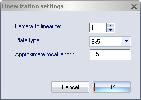
-
Select the number of the camera that you want to linearize with Camera to linearize.
Select the camera to linearize as the only camera in the 2D view before starting the linearization. The camera number in the dialog will be automatically set to that camera.
-
Make sure that you are using the correct plate type. The standard plate consists of 6x5 markers.
-
Enter the focal length of the current lens in Approximate focal length. This ensures that the distance intervals are scaled correctly when performing the linearization.
-
Click OK to start the linearization procedure.
-
The linearization procedure starts at the first distance interval, close to the camera.
-
Move the plate across the camera image while varying the orientation of the plate.
-
Use the feedback from QTM to make sure that you are at the correct distance of the camera.
-
Keep varying the position and the orientation of the linearization plate until all triangles have turned green.
-
-
When the first distance interval is done, the image will be reset, and the distance interval is changed to the next one, farther away from the camera.
-
Repeat the procedure at this distance, until all triangles have turned green.
-
-
The linearization procedure will automatically stop. QTM proceeds to perform the calculations and the results are shown in the Linearization results dialog.
-
In case you need to stop the linearization procedure before it has been finished automatically, for example if you need to change exposure settings, press the Esc button to quit.
During the linearization procedure, the lens must not be touched. However, the camera can be moved if needed.
Evaluating the linearization
When you are finished with the data collection, QTM will calculate the linearization parameters. The results are presented in the Linearization results dialog.
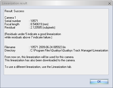
The dialog shows if the linearization has passed or failed. Furthermore, the dialog shows the following metrics for the linearized camera:
-
Focal length
The calculated focal length of the lens in mm. Make sure that the value corresponds to the lens specifications.
For underwater cameras, the calculated focal length will be about 30% larger than specified due to refraction.
-
Residual
The residual represents the remaining error of the collected data after application of the linearization in subpixels. The residual should be lower than 5 subpixels for standard camera-lens combinations. For wide-angle lenses, higher values may be acceptable.
Furthermore, the dialog shown information about the linearization file that has been generated. The file name consists of the serial number of the camera, followed by the date and time the linearization was performed. The linearization procedure outputs three files:
-
.lin - The linearization file that is used by QTM.
-
.stat - This file contains the settings of the linearization and also some statistics.
-
.qcl - This file contains the actual linearization measurement. It is only named with date and time.
The files are saved in the Linearization folder under the Qualisys program data, typically C:\ProgramData\Qualisys\Linearization. The .lin file is also uploaded to the camera.
Click OK to close the Linearization results dialog.