Connecting an Oqus system
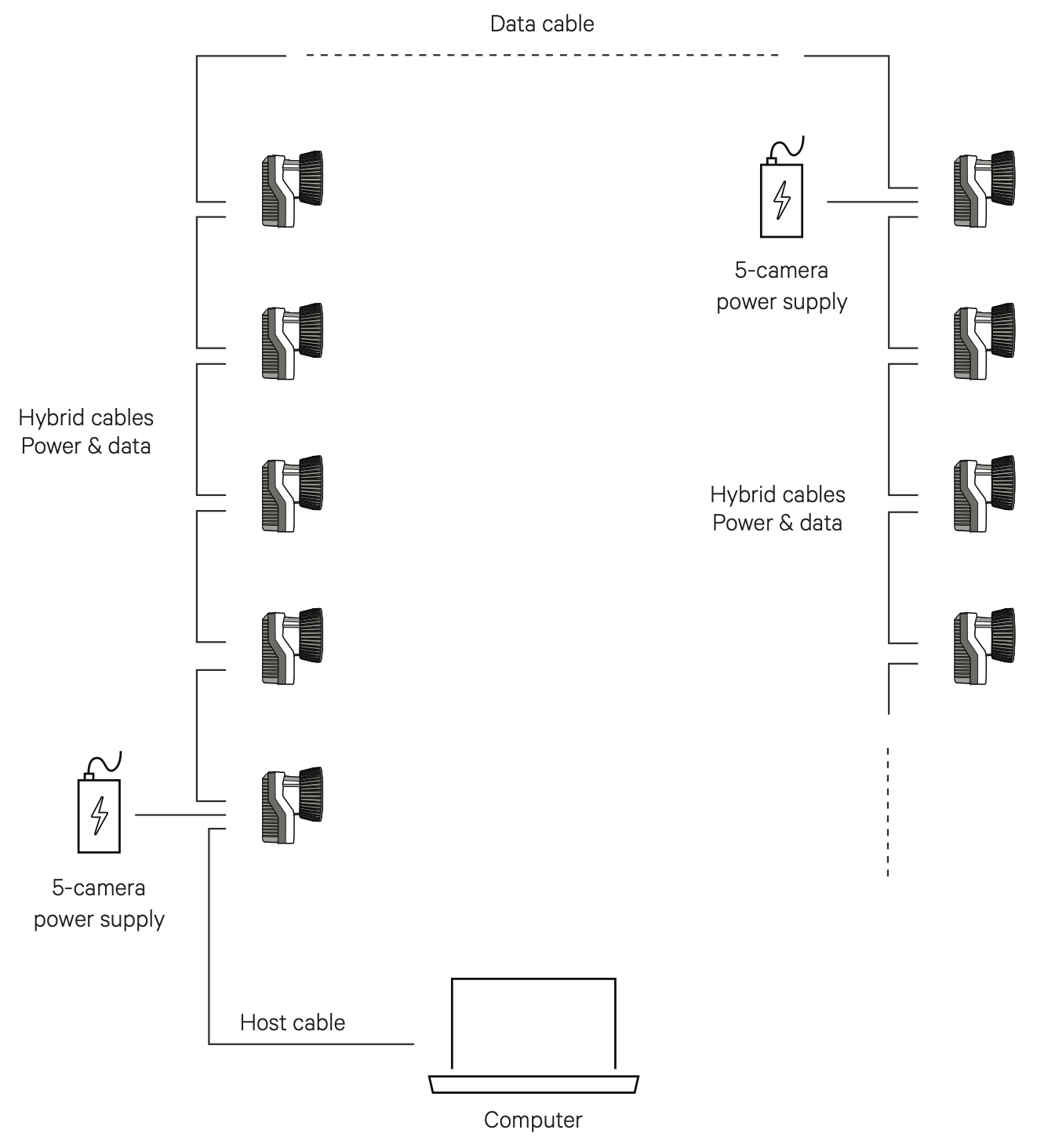
An Oqus system consists of the following components:
-
Oqus cameras
Oqus cameras of one or several types.
-
Hybrid Power/Data cables
Cables carrying both power and data between cameras.
-
Data cables
Cables carrying data between cameras.
-
Host cable
Cable carrying data between first camera in the chain and computer or switch.
-
One or more power supplies
One power supply can power up to five Oqus cameras.
-
Trigger/Sync splitter (optional)
A Trigger/Sync splitter cable can be connected to the Control port of an Oqus camera for synchronization with external devices. It is also possible to add a Camera Sync Unit to the system. However, this requires the use of an Ethernet switch.
-
Gigabit Ethernet switch (optional)
The use of a Gigabit Ethernet switch is required for systems with more than 15 Oqus cameras or if you have more than two Oqus 2c or Oqus high-speed video cameras.
The Oqus system is easy to connect. The connectors are unique and cannot be connected to the wrong ports. Further, the connector color matches that of the port. The DATA connector can be connected to any of the two DATA ports, and the POWER connector can be connected to any of the two POWER ports, so it does not matter on which side you put the connector. For more information on the connectors, see Oqus camera connectors.
When the cables have been connected correctly the LEDs on the back of the Oqus will be lit. The EXT LED will be lit green and the ACT LEDs will be blinking.
For larger systems, start a new power chain when the maximum of 5 cameras per power chain is reached. One of the POWER ports of the first camera of the new chain should be connected to a power supply. The DATA ports of the last camera of the previous chain and the first camera of the new chain are connected with a Data cable.
For Oqus systems larger than 15 cameras and for systems with many high-speed cameras, the performance can sometimes be improved with a Gigabit Ethernet switch and then connect the cameras in shorter daisy-chains, see Connecting a Qualisys system through an Ethernet switch.
Oqus startup sequence
Before you connect the camera system, make sure that the QDS (Qualisys DHCP server) is running and that the network interface settings are correct. This is needed for the cameras to receive an IP address from QDS to communicate with other Miqus cameras and the host computer. For more information, see QDS and Network card setup.
The general Oqus startup sequence is as follows.
-
Connect the power supply and the green LED on the front will blink twice.
-
After a few seconds the startup bar below is shown.
If the bar stops at two-thirds then the Oqus is waiting for an IP-address. The reason is probably either a missing connection to the computer or that QDS is not running, for instructions on how to search for the error see Troubleshooting connection.
-
When the camera has an IP-address the display will show an image similar to one below. The Oqus will first synchronize to other cameras, during that process the clock is blinking and there is a spinning plus sign instead of the letter M or S. Wait until the clock stopped blinking and the display shows M or S.
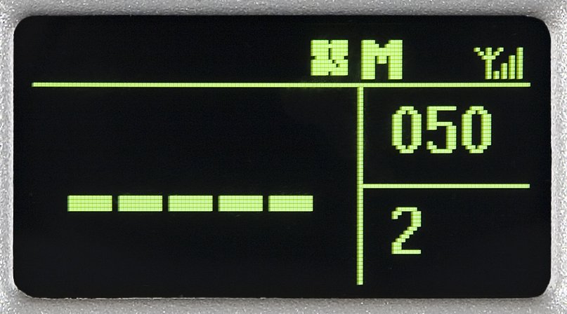
The M or S on the display stands for Master respectively Slave. This is only to show which camera that is sending a synchronization pulse to the other cameras.
Setting the aperture and focus
The Oqus 7+ with standard lens option has a motorized lens, which can be controlled from QTM via the Lens Control interface in the Camera Settings sidebar in the 2D View window, see Camera settings sidebar.
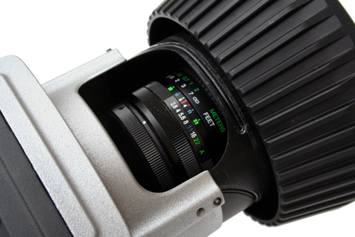
For Oqus cameras with a manual lens, you need to extend the strobe mechanics to get access to the focus and aperture rings of the lens.
-
Turn the strobe mechanics counterclockwise to expose the lens for adjustment.
-
When done, turn the strobe back (clockwise) to close it.
The strobe should always be in closed position during measurement to achieve the best strobe light distribution, and to make sure that the strobe does not block the peripheral view of the lens.
For general recommendations on settings aperture and focus, see chapter Tips on setting aperture and focus.
Setup Oqus system for wireless communication (deprecated)
The Oqus system can run with a wireless communication from the camera system to the computer. The camera uses the 802.11b/g@54mbps standard. However the communication speed can be reduced depending on the signal strength or if there are many other wireless networks.
Setting up Oqus for wireless communication requires that the wireless adapter of the computer is set up as a hosted network. This requires a computer running Windows 7. This feature is no longer supported for Windows 10 and higher. The configuration requires a special version of QDS, contact support@qualisys.com for more information.
From QTM 2019.3 wireless connection of an Oqus system is no longer supported by the included version of QDS. Please contact Qualisys support at support@qualisys.com for a special version of QDS if you need to connect an Oqus wireless camera to a wireless network.