Volumes in 3D views
QTM can help you see the volume in which you will be able to measure by calculating the covered and the calibrated volumes. The view cones can also be used for visualizing the FOV, see chapter Camera view cones in 3D views.
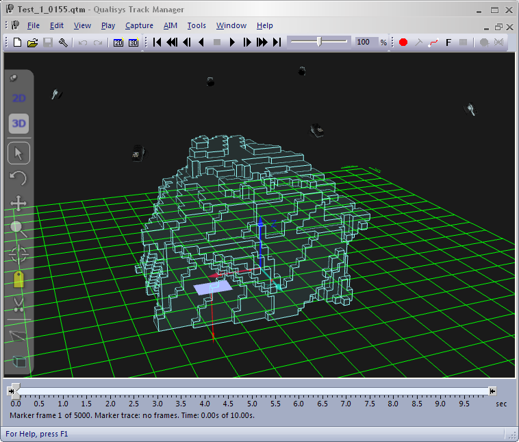
The covered volume is displayed as light blue cubes. It is the volume that is seen by a certain number of cameras, specified by the user with the Cameras required to consider volume covered setting on the 3D view settings page in the Project options dialog. The covered volume can be used to determine where 3D data can be measured and is calculated by combining the view cones and is therefore affected by the length of them, i.e. the Smallest marker size visible setting.
You can also use the Volume buttons on the GUI Control toolbar to toggle the display of the volumes.
-
The default marker size differs between the camera models. e.g. for Oqus 3-series the default marker size is 12 mm. The covered volume is also cut default by the floor level, but that can be changed by disabling the Cut covered volume at floor level option on the 3D view settings page in the Project options dialog.
-
The default required number of cameras is three cameras for calculating the covered volume, which most of the time gives the most likely covered volume. If you use only two cameras to calculate the volume there will be some parts that are actually very difficult to reach with the wand.
-
It is important to notice that the covered volume does not consider whether it is likely that markers are occluded by the subject or not. To simulate this you can use the camera selection in the Volumes menu see below.
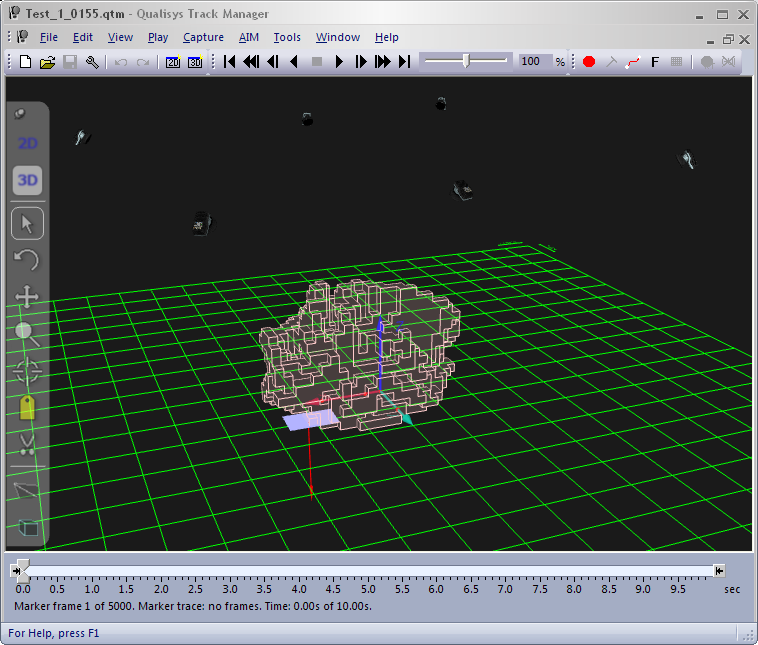
The calibrated volume is displayed as light red cubes. It is the volume that the wand moved through when the camera system was calibrated. It therefore indicates where the most accurate 3D results can be expected and can be used to evaluate if the wand needs to be moved in a larger volume. 3D data will however be calculated outside the calibrated volume as well. This is usually not a problem as long as the markers are within a few decimeters of the calibrated volume. Use the 3D residual to evaluate if the data is good enough.
The calibrated volume can only be displayed in files calibrated with a calibration file which is processed in QTM 2.3 or later.
The volumes can be enabled from the Volumes
menu on the 3D view toolbar. Click
on the Volumes button ![]() to open the dialog and enable the volumes
with the Show calibrated volume
checkbox and the Show covered volume
checkbox. The features can also be enabled on the 3D
view settings page in the Project
options dialog.
to open the dialog and enable the volumes
with the Show calibrated volume
checkbox and the Show covered volume
checkbox. The features can also be enabled on the 3D
view settings page in the Project
options dialog.
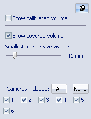
The maximum distance from the cameras is determined by the Smallest marker size visible setting, which defines the marker size that should be visible in the entire volume.
Select which cameras that are used in the calculation with the All/None buttons and camera check boxes. By choosing which cameras are considered when creating the covered volume, you can for example determine what happens to the volume when one camera is occluded. Another case that can be simulated is when the cameras are mounted on two sides and can only see markers on one side of the subject, e.g. on a human walking through the volume. Then you can turn off all of the cameras on one of the sides to see the volume where the subject can be viewed by the rest of the cameras.