Bertec calibration and settings
The following settings apply to Bertec analog force plates.
Bertec force plate calibration parameters
Select the Bertec force plate type and click Calibration under the Force plate type heading to go to the Bertec force plate calibration parameters dialog. It contains the settings for dimensions and calibration factors of the Bertec force plate.
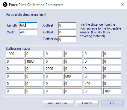
Dimensions
Under the Force plate dimensions heading you should enter the dimensions parameters for the Bertec force plate. The parameters can be found in the user manual of the Bertec force plate.
Calibration matrix
The Calibration matrix is used to calibrate the force plate. Enter the values of the calibration matrix, which is found in the manual of the Bertec force plate, under the Calibration matrix heading. Bertec often just supplies the six values of the diagonal in the matrix. The values can also be loaded with Load from file from the diskette, which is attached to the manual of the Bertec force plate.
Bertec force plate settings
Select the Bertec force plate type and click Settings under the Force plate type heading on the Force plate page to open the Bertec force plate settings dialog.
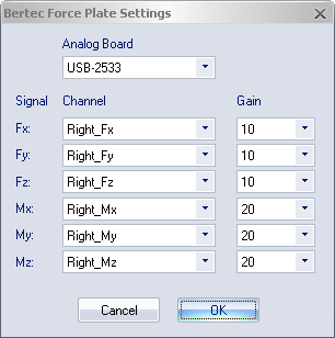
There are three settings on the dialog: Analog board, Channel and Gain, see example in image above.
-
Select the analog board where the force plate is connected from the Analog board drop-down list.
-
With Channel each signal is combined with its respective analog channel.
On the Analog board (...) page the channel names can be renamed to match the signal names.
-
The Gain is set to the gain of each channel as selected on the Bertec amplifier.
For more information about these settings see the manual of the Bertec force plate.