Fixed camera calibration
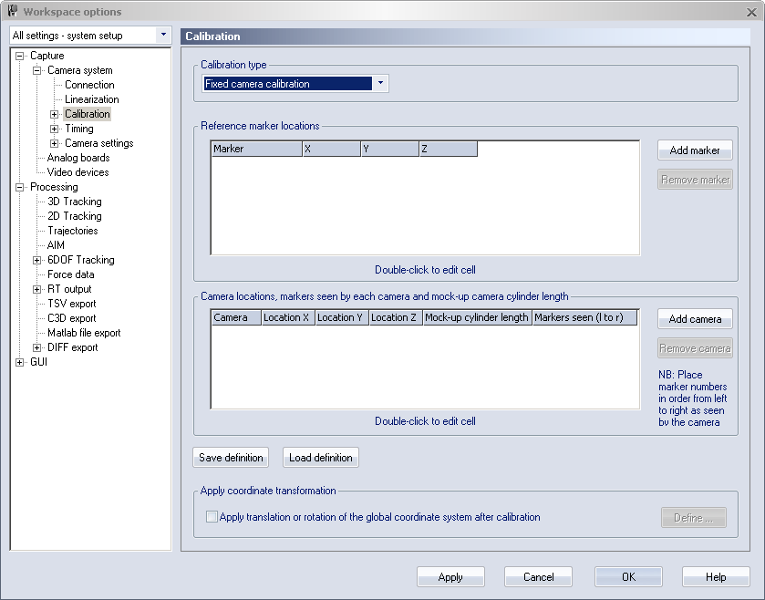
On the Calibration page for Fixed camera calibration you should enter the data from the survey measurement. If you cannot see this Calibration page change the Calibration type option to Fixed camera calibration. For more information about how to use the fixed camera calibration method, see chapter Fixed camera calibration method.
Use the options Save definition and Load definition to save respectively load the data for the Fixed camera calibration. The default folder is the project folder.
The first time you enter the survey data it must be entered manually.
Calibration type
Under the Calibration type, you can choose the following options:
-
Calibration type
Make sure that Calibration type is set to Fixed camera calibration if you want to use this calibration method.
-
Linearization
-
Use linearizations loaded in project/file: Use the linearizations that are currently loaded in the project. This allows you to use linearization files that differ from the linearizations that are stored in the cameras.
-
Use factory linearizations: Use the linearizations from the cameras.
Under most circumstances, the linearizations loaded in the project are the same as those stored in the cameras.
-
-
Validate
Check this option to validate the current calibration, rather than making a new calibration.
Reference marker locations
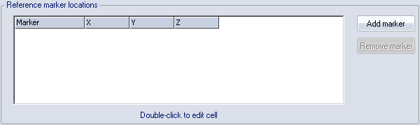
Under the Reference marker locations heading you should enter the survey data of the reference marker positions. Use the Add marker and Remove marker options to add or delete reference marker locations. Add the markers in the physical order from left to right. This will make it much easier to enter the markers seen by camera. Double-click the X, Y and Z locations of each marker to edit it.
All of the markers’ locations must be entered to make a successful Fixed camera calibration.
Camera locations and markers seen by each camera in order from left to right
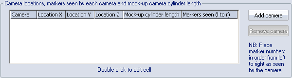
Under the Camera locations and markers seen by each camera in order from left to right heading you should enter the survey data of the camera positions. Use the Add camera to add a new camera last in the list. The cameras must be entered in the same order as the camera system. It is not possible to rearrange the cameras after they have been added, just to remove a camera with Remove camera. Double-click the column to enter the following data:
-
Location X, Location Y and Location Z
The survey measurement data of the camera.
-
Cylinder length
The length of the cylinder that was used on the camera dummy when making the survey measurement.
This length is the horizontal distance between the plate of the camera dummy and the front side of the cylinder.
-
Markers seen (l to r)
The markers seen by the camera. Enter them in order from left to right as seen by the camera and separate them with commas (the numbers refer to the first column in the Reference marker locations list).
QTM uses the top markers in the 2D view window as reference markers.
All of the cameras must be entered to make a successful Fixed camera calibration.
Apply coordinate transformation
![]()
With Apply coordinate transformation you can translate and rotate the global coordinate system to any desired position. Select the checkbox and then click Define to set the coordinate transformations on the Transformation page, see chapter Transformation.