2D tracking
![]()
The 2D tracking page contains settings for the 2D tracker. The 2D tracker uses the data of just one camera to calculate trajectories in a plane in the 3D view window, see chapter 2D tracking of data.
Tracking settings
![]()
Under the Tracking settings heading you can select the camera that will be tracked with the Camera to track option. Choose the camera from the drop-down list. You can only 2D track one camera at a time.
The option Turn on track filtering and remove unidentified tracks is very useful to limit the number of trajectories in the 2D tracking output. It filters the data so that short identified tracks and the 2D markers that have not been identified are not displayed as trajectories. Use the option Minimum length of identified tracks to set the minimum number of frames for an identified track in the 2D data to be transferred to a 3D trajectory.
If you turn off the filter the unidentified markers in the 2D data will be transferred to a 1 frame long trajectory. This means that the data will be very fragmented if the 2D tracker has left a lot of markers unidentified.
Auto join
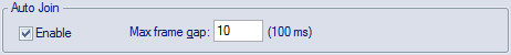
As soon as a marker is completely hidden during the measurement, even if it is just for one frame, a new trajectory will be started by the tracking function. The Auto join function examines the trajectories after the tracking to see if any can automatically be joined. The Max frame gap specifies the number of frames allowed between two trajectories that will be qualified for joining, the matching number of milliseconds with the current frequency is displayed next to the option. The Auto join function then uses the tracking parameters to decide if two trajectories can be joined.
The Auto join function is enabled by default with a value of 10 frames, and it can be used to make the identification easier.
Auto join only joins two trajectories so that they are one in the trajectory info windows. If you want to fill the gap between the two trajectories with data you need to use the gap-fill function, see chapter Trajectories.
2D to 3D settings
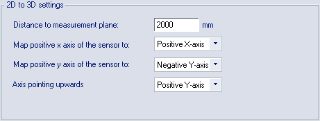
The 2D to 3D settings heading contains settings for how the 2D data is displayed in 3D view window.
-
Distance to measurement plane
Set the distance from the camera sensor to the measurement plane in mm. The measurement plane will be the same as the green grid in the 3D view window. With this setting you can get the distances in the 3D view window to match the real distances. You must measure the distance yourself, but for most applications the accuracy of the distance does not have to be better than in cm.
-
Map positive x axis of the sensor to
Select the axis that will map to the positive x axis of the sensor, i.e. to the right if looking in the direction of the camera. Choose the axis from the drop-down list.
-
Map positive y axis of the sensor to
Select the axis that will map to the positive y axis of the sensor, i.e. downwards in the camera view. Choose the axis from the drop-down list.
-
Axis pointing upwards
Select the axis that will be pointing upwards. Choose the axis from the drop-down list. With this setting you can move the camera in the 3D view so that it looks from different directions, i.e. from the side, from above or from below.