How to use gaze vectors in QTM
Setting up a gaze vector in QTM
After connecting and setting up a Tobii eye tracker device, follow these steps to add a gaze vector in QTM.
-
Go to the Gaze Vector page under Project Options > Processing. For an overview of the gaze vector options, see Gaze vector settings.
-
Click on Add to add a new gaze vector. The gaze vector includes the definition for both left and right eye.
-
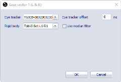
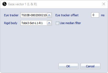
Double click on the gaze vector to open the Gaze vector dialog.
-
Select the eye tracker device from the Eye Tracker drop-down list.
-
Associate a rigid body with the eye tracker. The rigid body is needed to project the gaze vector in the 3D space. You can select the rigid body from the Rigid body drop-down list.
-
The list contains a list with predefined rigid bodies for the selected Tobii eye tracker, see chapter Tobii rigid body definitions for more information.
-
It is also possible to choose a custom rigid body from the rigid bodies that are included on the 6DOF Tracking page, for example if you want to use a refined rigid body definition.
-
For tips on how to optimize the tracking of the glasses, see chapter Tips for improving the tracking of the glasses.
-
-
If you are not using hardware synchronization you can specify an offset to compensate for the latency of the recorded eye tracker data.
-
For tips on how to estimate the latency, see chapter Tips for compensating latency.
-
-
Optionally, check the Use median filter option for smoothing the gaze position and gaze vector data.
-
On the Processing page under Project Options, make sure that the processing steps Calculate 6DOF and Calculate gaze vector data are selected for both Real time actions and Capture actions.
Tobii rigid body definitions
The Qualisys-Tobii connectivity kits for Tobii 2 and Tobii 3 include marker sets that can be attached to the glasses. QTM includes predefined rigid body definitions corresponding to the available attachments, that can be chosen from the rigid body drop-down list in the gaze vector definition dialog.
-
For Tobii Pro Glasses 2, three sets with different layouts are available. The layout number is specified on the box containing the kit items. The predefined rigid body definitions in QTM are named Tobii Layout x, where x needs to be replaced with the layout number.
-
For Tobii Pro Glasses 3 there are separate attachments for the left and the right side of the glasses. The marker set number is specified on the box containing the kit items. When you have multiple glasses, the left and right attachments can be used in four different combinations. The predefined rigid body definitions in QTM are named Tobii3-Set-Lx-Ry, where x and y need to be replaced with the respective set numbers. Left (L) and Right (R) are considered from the perspective of the person wearing the glasses.
Tips for improving the tracking of the glasses
The predefined rigid body definitions in QTM for the Tobii marker attachments give a good starting point for tracking the glasses. However, the actual marker positions may deviate from the predefined ones, which may lead to suboptimal tracking results.
The tracking can be improved in the following ways:
-
Create a refined rigid body definition (see section below).
-
Add a marker to the rigid body used to track the glasses, or remove one, to make it more asymmetric.
-
In some cases it can also help to use an AIM model for labeling the markers, for example to avoid swapping of the left and right clusters in QTM.
Refinement of the Tobii rigid body definition
Instead of following the steps below, you can use the Refine rigid body script, that is included with the scripting tools at https://github.com/qualisys/qtm-scripting.
To refine the Tobii rigid body definition, follow these steps:
-
Make a short capture with the Tobii glasses with the original rigid body definition. If you want to add extra markers, make sure they are included in the capture.
-
Select a range on the time line with good quality tracking and make sure that the Tobii lay out trajectories are correctly labeled. The 6DOF data should be present. Check that the local axes are correct: the Z axis should point forward from the glasses and the Y axis should point up.
-
After manual changes of the trajectories you need to reprocess the file with the Calculate 6DOF option enabled.
-
In case 6DOF data is missing despite the labeling is correct, reprocess the data with a larger bone length tolerance of 10-15 mm in the 6DOF setting.
-
-
Select the trajectories of the glasses, right click the selection, and choose Define rigid body (6DOF) (choose Average of frames if you have checked the tracking and labeling quality across the selected time range). Give the rigid body a different name (for example "Tobii-refined").
After adding the new definition, you will need to correct the definition as follows.
-
Open the 6DOF Tracking page under Project Options.
-
Select the new rigid body (from now on called Tobii-refined)
-
Press the Translate button, choose the option To current position of this rigid body, and select the predefined Tobii rigid body. Press OK twice (Translate dialog and Project Options).
-
Reprocess the file with the Calculate 6DOF option enabled and select 6DOF settings from project.
-
Go back to the 6DOF Tracking page under Project Options and select the Tobii-refined rigid body.
-
Press the Rotate button, choose the option Rotate as this rigid body, and select the predefined Tobii rigid body. Press OK twice (Rotate dialog and Project Options).
-
Reprocess the file, make sure to check the Calculate 6DOF option and select 6DOF settings from project.
-
Check in the 3D View window that the local axes of the two rigid bodies perfectly overlap.
Now you have a refined rigid body definition, make sure it is used for the eye tracker.
-
Open the Gaze Vector page under Project Options and select it as the rigid body for your Tobii eye tracker.
-
Open the 6DOF Tracking page under Project Options, set the Bone length tolerance value to 5 mm, and remove the unused rigid body definitions.
Tips for compensating latency
When not using hardware synchronization, there will be a certain latency of the recorded Tobii eye tracker data. The latency needs be compensated in QTM for a correct calculation of the gaze vector.
The latency may be dependent on a number of factors, such as the network connection or simultaneous use of the Tobii Glasses Controller software. When using multiple Tobii Glasses 3 devices, the latency increases for the subsequent devices since they are started sequentially.
The latency can be estimated as follows:
-
In QTM, configure the gaze vector using no rigid body and zero offset.
-
Make a capture with the glasses on. During the capture, look at a fixed point, for example a marker in front of you, while gently shaking or nodding your head.
-
Create a plot of the pitch or roll angle of the Tobii 6DOF data and another plot of the gaze vector data, and align the plots.
-
The latency can be estimated by measuring the delay between the peaks in the 6DOF angle and the corresponding peaks in the gaze vector.
-
-
Reprocess the gaze vector data with the estimated latency.
-
For Tobii Glasses 2 the latency is specified by the Offset value (in milliseconds) in the Input device settings page.
-
For Tobii Glasses 3, the latency is specified by the Eye tracker offset value (in milliseconds) in the Gaze vector dialog.
-
-
Check if the peaks of the rigid body angle and the gaze vector are aligned now.
-
If the peaks are aligned you have found the correct estimate.
-
-
When you reprocess the gaze vector data associated with the rigid body definition of the glasses, the gaze vector should point at the fixed position you were looking at during the capture.
To make sure that the latency is consistent, capture a number of trials and check that the latency compensation is correct for all trials.
The latency compensation is only applied to the gaze vector calculation in QTM. The recorded eye tracker data or analog data from the Tobii device is not affected by the compensation.