Setting up Tobii Pro Glasses 3 in QTM
Set up and configuration in QTM
For using the Tobii Pro Glasses 3 with QTM, the QTM computer and the Tobii Recording unit must be connected to the same local network. For connecting and setting up your Glasses 3 device, follow the instructions at connect.tobiipro.com. You will also need to install the Glasses 3 Controller application, which you can download from the Tobii website (link included in the instructions at connect.tobiipro.com).
Connecting a single Glasses 3 device
For connecting a single Glasses 3 device for use with QTM, the following connection options can be used.
-
WiFi access point: connect the QTM computer to the network with name "TG03B-XXXXXXXXXX" (serial number of Recording unit). Default password: TobiiGlasses.
-
Cable (router): Connect the Tobii recorder with an Ethernet cable to a router. When using a wireless router, the computer running QTM can be connected via WiFi.
For a detailed description of the connection options, refer to the Connection Guide in the Glasses 3 Controller application.
After connection the Glasses 3 device it should be accessible in the Glasses 3 Controller application.
The connection option Cable (direct) cannot be used in combination with QTM, because then the Glasses 3 device will not get an IP address.
Connecting multiple Glasses 3 devices
For connecting multiple Glasses 3 devices for use with QTM, the following connection options can be used.
-
Cable (router): Connect the Tobii Recorder units with an Ethernet cable to a router. When using a wireless router, the computer running QTM can be connected via WiFi.
-
Alternatively, the Tobii Recorder units can be connected wireless through a WiFi router. This requires setting up an alternative network configuration on the Tobii Recorder devices.
For a detailed description of the connection options, refer to the Connection Guide in the Glasses 3 Controller application or other Tobii resources.
After connection the Glasses 3 devices they should be accessible in the Glasses 3 Controller application.
For setting up a wireless connection to a router, you can add a network configuration to the Tobii device via the web interface. To access the web interface, open a browser and type http://tg03b-xxxxxxxxxx (serial number of Recorder unit) in the browser's address bar. For more information about the Glasses 3 web interface, contact Tobii support.
Adding Tobii Pro Glasses 3 to QTM
To set up the glasses as an input device in QTM, follow these steps:
-
Open the Project Options and navigate to the Input Devices page.
-
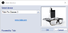
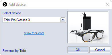
On the Input Devices page, click the Add Device button.
-
In the Add Device dialog, select Tobii Pro Glasses 3 from the Select device drop down menu.
-
Open the Tobii Pro Glasses 3 settings page under Project Options > Input Devices > Eye Trackers.
-
Press the Locate Glasses button. After a short while the connected Glasses 3 devices should be shown in the settings list.
Tobii Pro Glasses 3 device settings
The Glasses 3 settings are shown on the Tobii Pro Glasses 3 settings page under Project Options > Input Devices > Eye Trackers.

The settings page contains a list of the connected Glasses 3 devices and their settings. The device properties include information about the connection and the hardware, including serial numbers and firmware version, and a list of available data channels. The following properties can be set:
-
Gaze Frequency
The default Gaze frequency is 50 Hz. The Gaze frequency can be set for Glasses 3 devices if they support higher sample frequencies. -
Hardware Synchronized
Enable synchronized capture start between QTM and Tobii glasses. See chapter Setting up hardware synchronization with Tobii Pro Glasses 3 for how to set up hardware synchronization.
When the glasses are connected and set up in QTM, you can proceed to add a gaze vector, see chapter How to use gaze vectors in QTM.
Calibrating the glasses
At the start of a recording session, the glasses need to be calibrated to make sure that the gaze data is accurate. The calibration can be done in the Glasses 3 Controller application. For more information, refer to Tobii documentation.
Alternatively, the glasses can be calibrated via the web interface of the Tobii Glasses 3 device. To access the web interface, open a browser and type http://tg03b-xxxxxxxxxx (serial number of Recorder unit) in the browser's address bar. For more information about the Glasses 3 web interface, contact Tobii support.
Latency information
The Tobii data stream arrives to QTM over the network with a certain latency. This will affect the real time calculation of the gaze vector. For reliable synchronization of captured data, it is recommended to use hardware synchronization. If you cannot use hardware synchronization, you can estimate the latency as outlined in chapter Tips for compensating latency. When not using hardware synchronization or when using the Tobii data in real time, please take note of the following:
-
The latency of Tobii data may vary between trials.
-
The latency of the Tobii device data (e.g. pupil data), stored as analog data in QTM is not compensated for when applying latency compensation to the gaze vector calculation.
-
The latency may increase when using Glasses 3 software to record data and stream video from the Tobii glasses.
-
When using multiple glasses, latencies can be quite large (e.g. up to a few seconds) and may differ between devices.
-
The latency may depend on the quality of the network.
Setting up hardware synchronization with Tobii Pro Glasses 3
If you want to make sure that the data from the Tobii glasses is synchronized with the motion capture data, you can use the hardware synchronization for a simultaneous start of the recording.
The following items are required for hardware synchronization:
-
A synchronization cable included in the Tobii-Qualisys connectivity kit.
-
A Camera Sync Unit for Arqus of Miqus systems.
Set up the connections as follows:
-
Use a BNC cable to connect the Tobii sync cable to one of the Synchronization Output ports (Out 1 or Out 2) on the Camera Sync Unit. For an Oqus system, use the Sync out connector on a sync/trigger splitter cable instead of a Camera Sync Unit output port.
-
Connect the 3.5 mm connector of the Tobii sync cable to the Data synchronization port on the Tobii recorder.
-
In the Synchronization settings under Project Options > Input Devices > Camera system:
-
Set the Output mode to System live time.
-
The TTL signal polarity can be set to any value (Negative or Positive).
-
The synchronization connection is only needed at the start of the capture. After starting the capture, the synchronization cable may be disconnected.
Hardware synchronization and offset compensation is only applied to captured data. It is not possible to compensate for latency in real time.