Installing drivers for the A/D board
The Instacal software (drivers for the A/D board) must be installed on the computer before the installation of the hardware. Instacal is included in the QTM installer. Alternatively, the latest version of Instacal can always be downloaded from www.mccdaq.com.
After Instacal has been installed you can go on to install and configure your A/D board.
-
For the 64-channel USB-2533 board, see chapter Installing the USB-2533 board.
-
For the 16-channel USB-1608G board, see chapter Installing the USB-1608G board.
For more information about InstaCal read the README.TXT file from Measurement Computing that is put in the folder for the Instacal software.
Installing the USB-2533 board
Follow this procedure to install the USB-2533 A/D board:
-
Connect the supplied power supply to the POWER connection. It is important to connect the power supply before the USB, because when power adapter is connected to the board it cannot get the power from the USB connector. With a laptop the power supply must always be used otherwise the analog board will not start.
-
Connect the USB port on the analog board to an USB port on the measurement computer.
-
In case the Found New Hardware Wizard is opened, follow these steps. First, the wizard installs the MCC USB2 Loader Device and then it installs USB-2533 board. In the installation use the options No, not this time and Install the software automatically (Recommended). When done, restart the computer.
-
Run the Instacal software on the Windows Start menu.
-
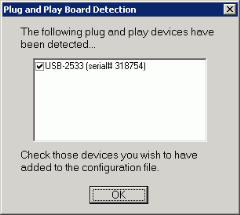
Instacal will detect the USB A/D board and display the following dialog.
-
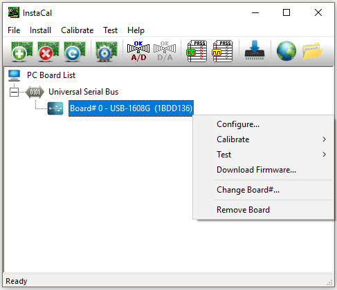
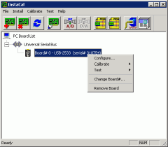
Click OK. The board will then be listed in Instacal as shown below.
-
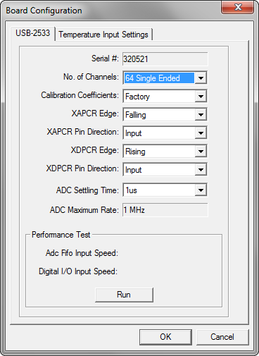
Right-click on the board and then click on Configure. Then change No. of Channels to 64 Single Ended. The reason for using single ended is among other things that force plates usually have this type of signal output.
It is possible to run this board in differential mode. However the wiring inside the connection box has not been optimized for differential signals. For differential signals HI and Lo is separated by 8 channels, e.g. Channel 1 HI and LO would be connected to Ch. 1 respectively Ch. 9.
It is important to check that the XAPCR Edge setting matches the setting for the Synchronization output on the Synchronization page in the Project options dialog. The default TTL signal polarity is Negative which matches XAPCR Edge = Falling.
Keep the XAPCR Pin Direction setting to Input. Changing this setting may cause damage to the board or to the camera.

-
Click OK and then exit Instacal.


When the board is properly installed it will be listed on the Input devices page in the Project options dialog in QTM.
Installing the USB-1608G board
Installing the USB-1608G board requires that InstaCal has been installed on the computer. If needed, reinstall QTM with the InstaCal option checked. Follow this procedure to install the USB A/D board:
-
Connect the USB-1608G board to USB port.
-
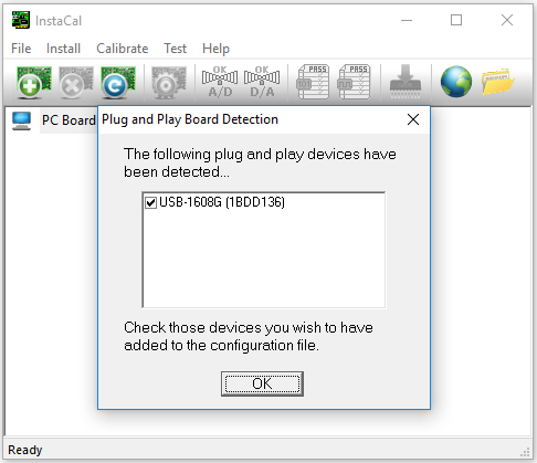
Start InstaCal via the Windows start menu.
-
The USB-1608G board should appear in the plug and play dialog. Click OK.

-
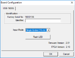
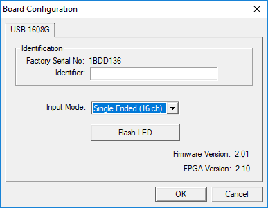
Open the configuration dialog (double click or right click and select "Configure").

-
Set "Input mode" to "Single Ended (16 ch).