Creating a 6DoF model in QTM
Once your object is set up with markers, you can create a model for it in QTM.
Begin by capturing a short measurement to record the position of the markers.:
-
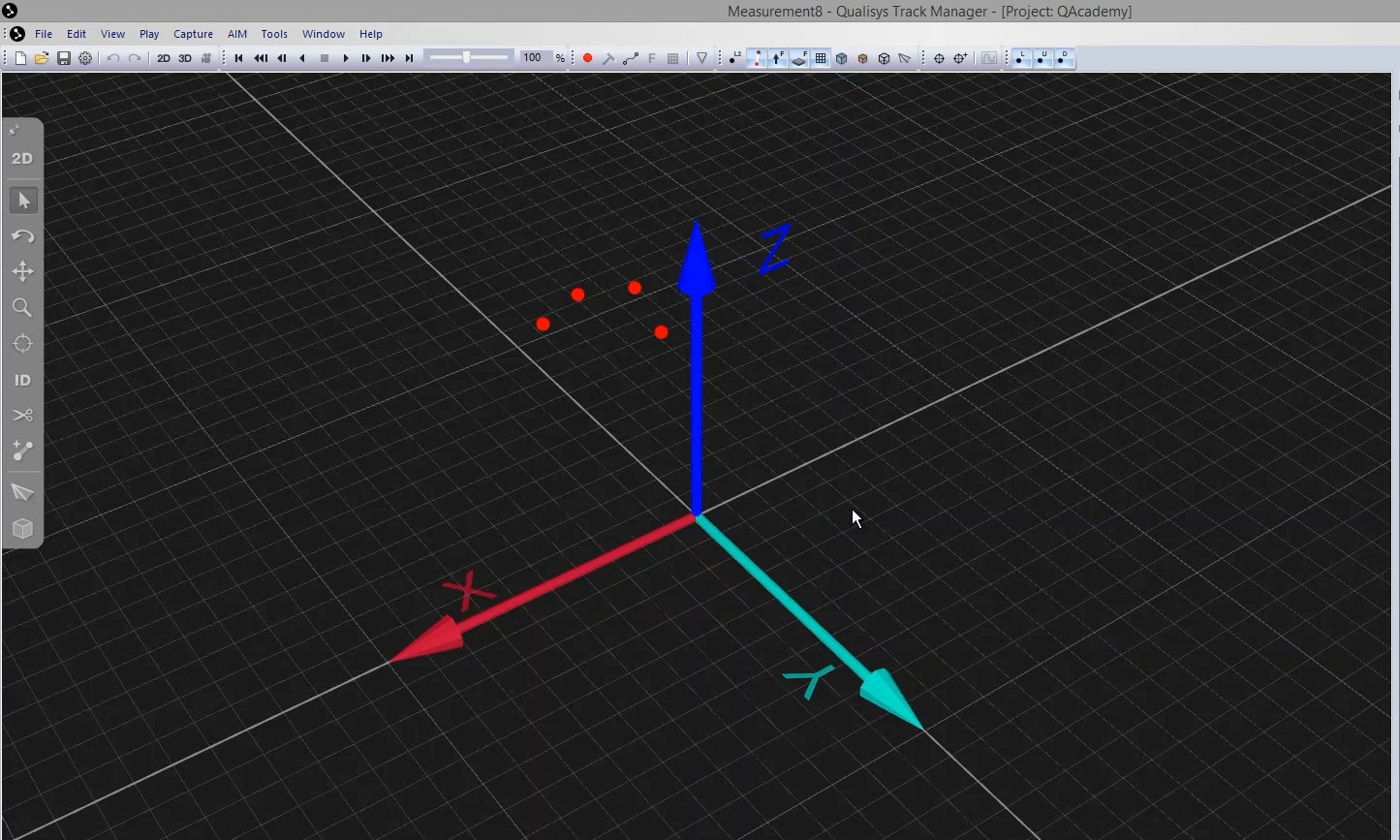
Start a new session (Ctrl+N), and switch the view to 3D (3) to confirm that all of the markers on your object are showing on screen.
-
In the top bar of QTM, click on the capture icon or use the keyboard shortcut Ctrl+M.

-
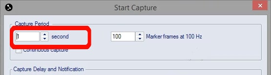
Set the Capture Period for one second, and click “Start.”
-
The capture will stop automatically, and QTM will show you the recorded trial with the markers still displayed as unidentified.
The next step is to create the rigid body in QTM:
-
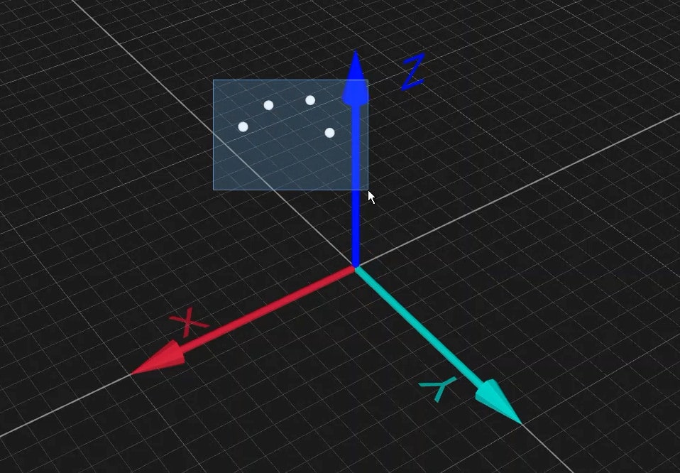
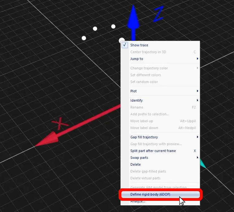
Select all of the rigid body markers by holding down the Ctrl key while clicking on them or by pressing the Shift key while drawing a box around them.
-
Right-click on any one of them and select “Define rigid body (6DOF).”
-
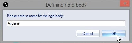
In the window that pops up, enter a name for the rigid body and click “OK.”
- QTM will process the data and let you know that the new body definition has been added. Click “OK.”
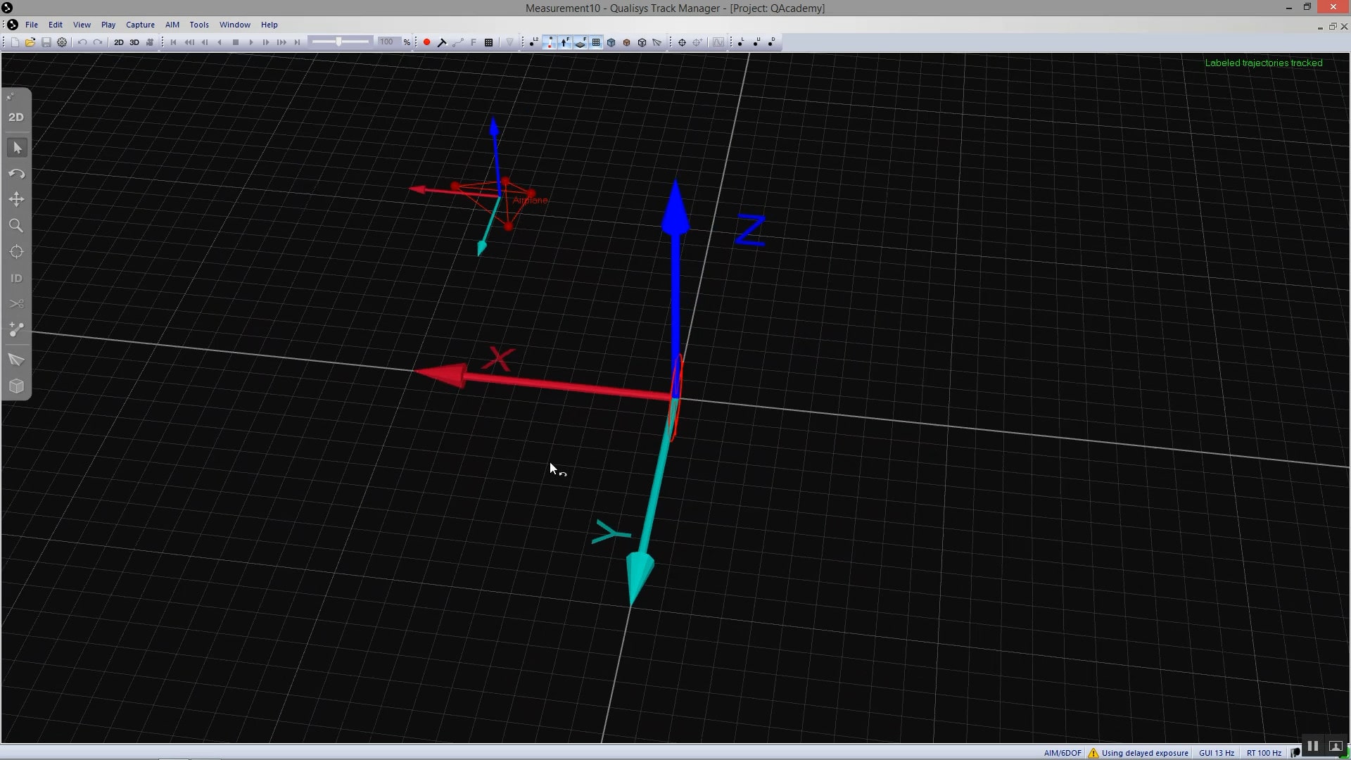
You will now see the markers on screen connected to each other and displaying their own coordinate system. The rigid body has automatically been added to your project. Now, if you switch back to the live camera view (Ctrl+N), you will see QTM tracking the rigid body in real time.
If at any point the rigid body markers on screen are disconnected and do not show their own coordinate systems, you can tell QTM to use the rigid body definitions:
-
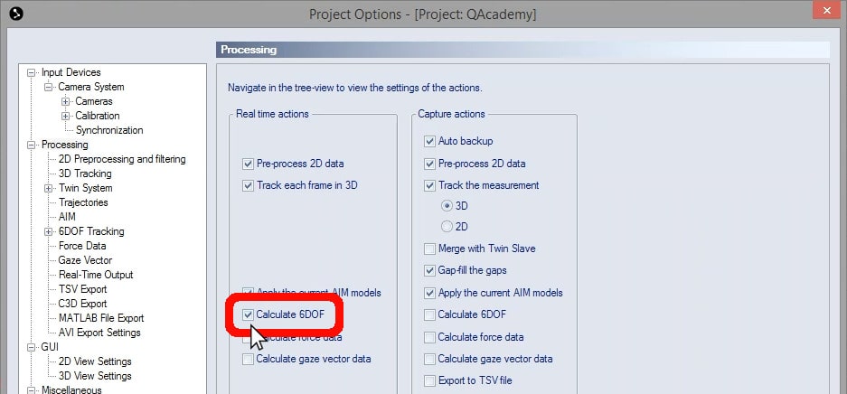
Open Project Options (keyboard shortcut Ctrl+W), and navigate to “Processing.”
-
In the column under “Real time actions,” click the check box to select “Calculate 6DOF,” then click “OK.”