Rigid body settings
Once a rigid body has been created, you can view its details and adjust the settings.
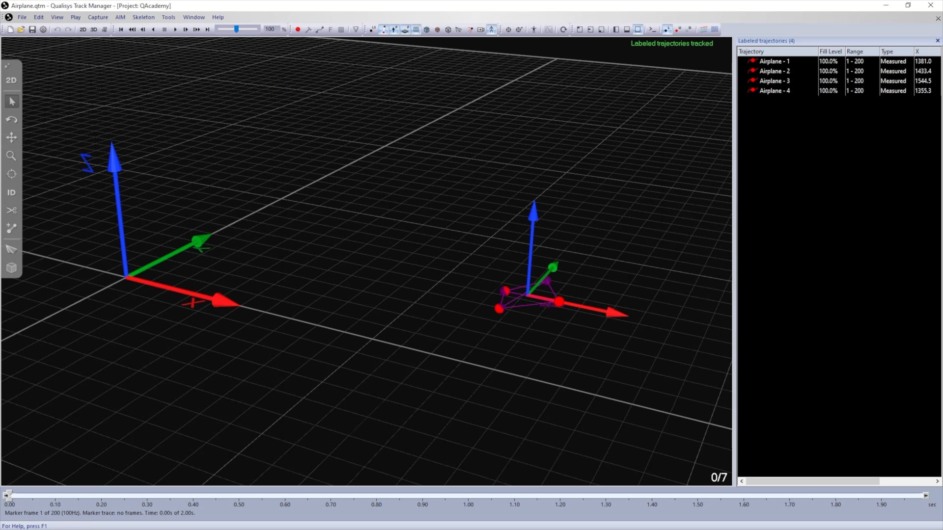
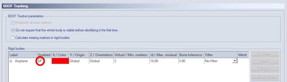
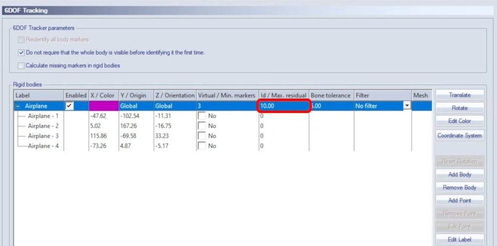
Open Project Options and navigate to “Processing” à “6DOF Tracking,” where all of the rigid body definitions in your project are listed.
![]()
-
The checkbox beside each rigid body lets you enable or disable its tracking.
-
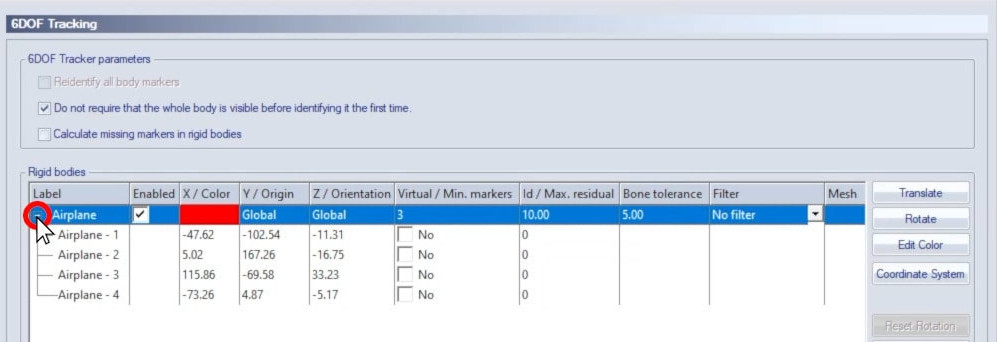
You can expand the label beside a rigid body to show the individual points that make up the body.
-
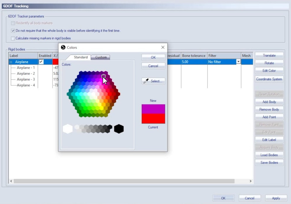
Double-clicking on the color of a rigid body will let you select a new color for display in the 3D viewer.
-
Below “Max. residual,” you can change the maximum residual accepted for 6DOF tracking of the rigid body.
-
Below “Bone tolerance,” you can specify how much variation is acceptable between the marker connections as defined in the rigid body and the ones actually being tracked. For example, if the bone tolerance is set to 5 millimeters but two of the markers are tracked 6 millimeters farther apart than they were when the rigid body was defined, QTM will not recognize them as part of it.
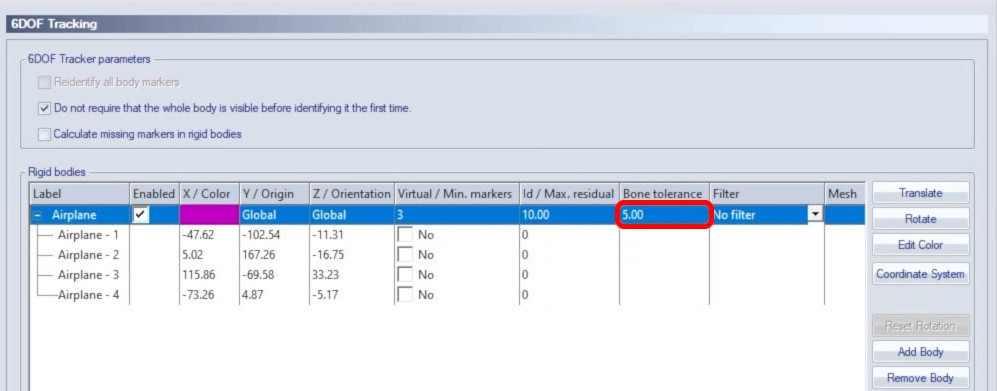
Try increasing the bone tolerance if your 6DOF body cannot be found or decreasing it if the body is found but the orientation is incorrect.
-
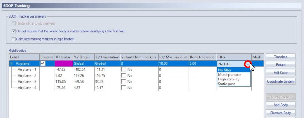
Below “Filter,” you can apply a smoothing filter to stabilize noisy data. The multi-purpose filter provides light smoothing and jitter reduction with minimum side effects. The high stability option applies strong smoothing, which can be useful in some situations but can cause data lag. The static filter reduces the jitter for immobile objects.
-
Once you click “OK,” your updated rigid body settings will be applied in real time and to newly captured data.
You can apply your updated settings to a previously recorded file by reprocessing it:
-
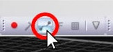
Click the reprocessing icon in the top toolbar or type the keyboard shortcut Ctrl+Shift+R.
-
In the File Reprocessing window, select only “Calculate 6DOF” and choose the 6DOF settings from the project.
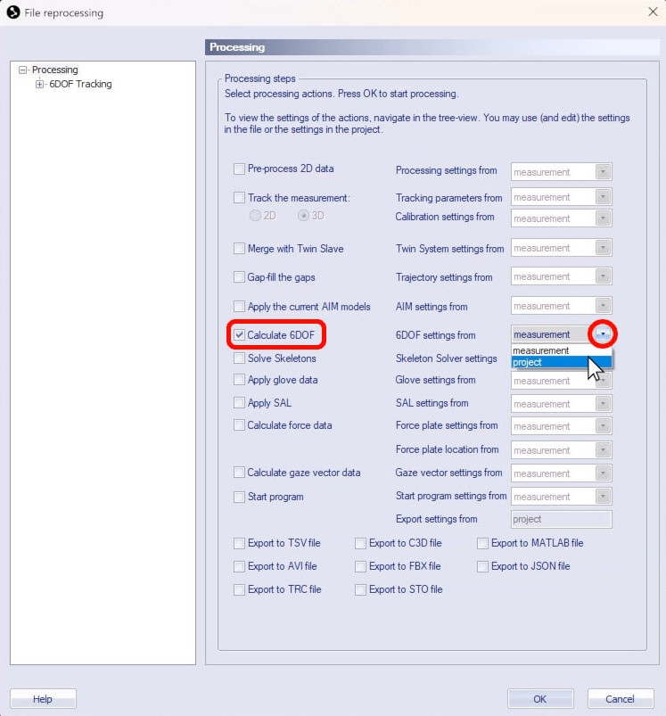
-
Click “OK,” and QTM will reprocess the file with your updated rigid body settings.