Defining a rigid body in QTM
Once the markers have been placed on the object, you can create a rigid body definition for it in QTM.
First, check that QTM is set to automatically calculate rigid body data:
-
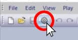
Open Project Options by clicking the gear icon in the top toolbar or by typing the keyboard shortcut Ctrl+W.
-
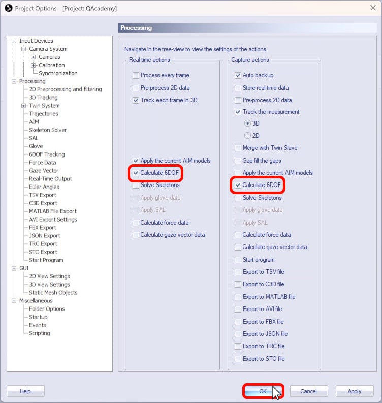
Navigate to “Processing.”

-
Make sure that “Calculate 6DOF” is selected in both columns and click “OK.”
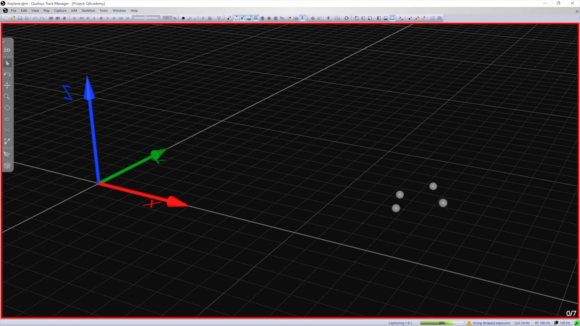
Next, capture a short measurement of the object:
-
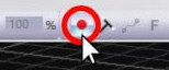 Click the capture icon in the top toolbar or type the keyboard shortcut Ctrl+M.
 -
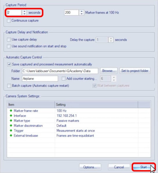
In the Start Capture dialog, set a brief capture period and click “Start.”
-
The object does not need to move during the capture; it is only important that all the markers be recorded.
-
Check the recorded file to make sure that the trajectories are tracked well and label them if desired.
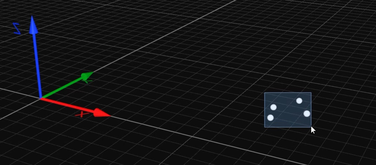
With the recorded file open, you can now create a rigid body definition:
-
Select all of the markers to be included in the rigid body while holding down the Shift key.
-
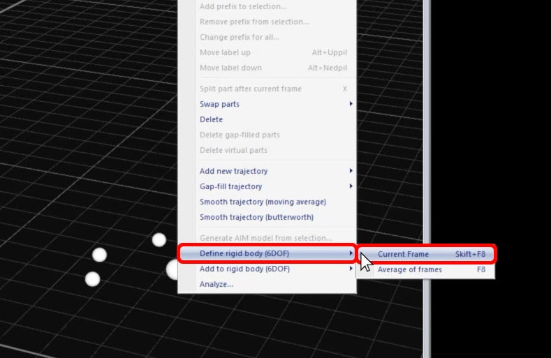
Right-click on the selection, click “Define rigid body (6DOF),” and select between “Current Frame” (keyboard shortcut Shift+F8) and “Average of frames” (keyboard shortcut F8).
-
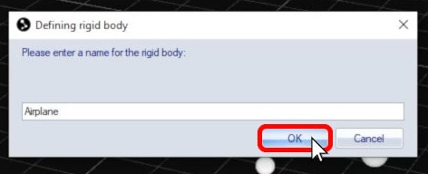
Input a name for the rigid body and click “OK.”
-
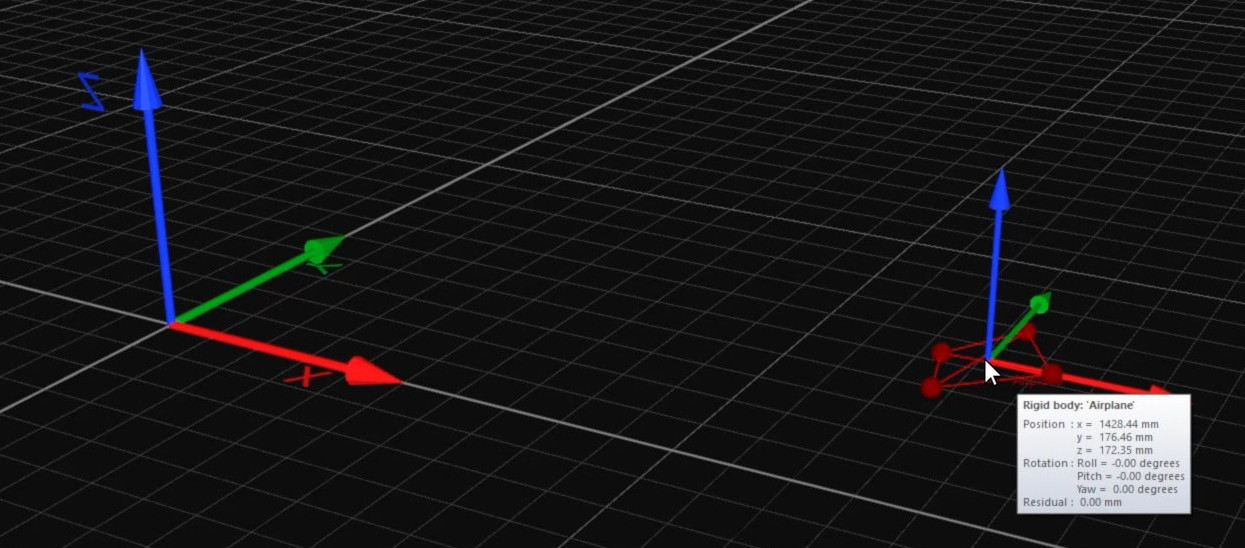
QTM will add the new body definition to your file, and the 3D viewer will now display the markers connected to each other with their own coordinate system.
The same trajectories can be used to define multiple rigid bodies as long as their labels don’t change. This can be useful, for example, in tracking bodies with different local coordinate systems.
Note that there are a few other ways to add a rigid body to QTM, such as loading a file or manually defining the points. You can find further details in the QTM user manual.