Visual3D is a software by HAS-Motion (www.has-motion.com) that can be used to convert the marker data collected with the Qualisys Track Manager (QTM) into variables such as joint angles.
One key component of the analysis in Visual3D is the model. It is based on a static trial that contains no body movement, with the person in a pre-defined body position. Based on this trial, the major body segments are re-constructed using the positions of markers placed in anatomical positions (Cappozzo, Della Croce, Leardini, & Chiari, 2005). Each of these segments is assumed to be rigid and represented by a segment coordinate system. For the dynamic trials, the position and orientation of each segment is reconstructed for each frame based on tracking markers that are attached to the segment.
In case of the Skinmarker model that is used for the running analysis, the static (defining) and tracking markers are identical.
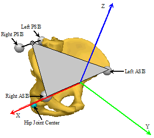
The origin of the pelvis segment is the mid-point between the L_IAS and R_IAS markers. Together with the SACR marker, the two IAS markers define the orientation of the pelvis. As a consequence of this, the pelvis tilt angle will be approximately 15-20 degrees when the person is standing upright.
In the Skinmarker model, Visual3D uses the distance between the IAS markers to re-construct the position of the hip joint centres based on regression equations (Bell, Brand, & Pedersen, 1989; Bell, Pedersen, & Brand, 1990).
(Image source: HAS-Motion Wiki, https://wiki.has-motion.com/doku.php?id=visual3d:documentation:modeling:segments:coda_pelvis)
The longitudinal axis of the thigh is defined by the hip joint centre (see above) and the knee joint centre. The knee joint center is calculated using the first running trial and a functional method based on work published by Schwartz, Rozumalski 2005. Markers located on the thigh and the shank are used to calculate knee joint axis. Once the axis of rotation is found, the knee joint center is located at a predicted distance from the FLE marker using the work of Drillis et al. (1966) and Mukhopadhyay et al. (2010). For details on Visual3D calculation of functional knee joint please refere to https://wiki.has-motion.com/doku.php?id=visual3d:tutorials:modeling:functional_joints.If functional joint calculation method provides inconsistent data user can switch off the functional joint calculation in settings.php. In that case the knee joint centre is created as a virtual landmark with an offset relative to the lateral knee marker. This offset is based on factors provided in the literature (Gardner & Clippinger, 1969) with some adjustments, scaled by the distance between the lateral knee and ankle markers. The adjustments are identical for all participants.
The orientation is defined by the superior patella marker (L/R_PAS), which sets the anterior direction.
The longitudinal axis of the shank is defined by the knee joint centre (see above) and the ankle joint centre. The ankle joint centre is a virtual landmark with an offset relative to the lateral ankle marker. Offset is derived from this regression equation: RSK_Proximal_Radius * 0.322 + 0.019373. Equation is based on unpublished data of physical measurement of knee and ankle width of 929 people.
The orientation is defined by the marker on the tibial tuberosity (L/R_TTC), which will be anterior relative to the longitudinal axis.
Each foot is represented by two coordinate systems that differ in their orientation.
First coordinate system (Left/Right Foot or L/RFT) is defined by a line connecting the ankle joint (see Shank above) and the marker on second metatarsal. The marker on fifth metatarsal serves as the lateral landmark to define the orientation of the segment. This segment has kinetic properties while the following segment are used as kinematic only segment.
The second representation of the foot (L/RMF) which is used in foot angle calculations is defined by the heel and second metatarsal markers but anterior axis is defined by virtual marker placed anterior above second metatarsal marker in the global coordinate system. This segment is subsequently used for calculation of angles. By default L/RMF orientation is normalized to static trial, it means that foot position in static trial is considered neutral (long axis parallel to the floor). In order to switch of this normalization go to [QTM project folder]\Templates\settings.php and change 'foot_normalized_to_static' => false.
Distal end of the longitudinal axis of thorax is defined by midpoint created by sacrum (SACR) and the midpoint of L_IAS and R_IAS. Proximal end of the longitudinal axis of thorax is defined by midpoint of sternum – manubriosternal edge (SME) to spinous process of the 2nd thoracic vertebra (TV2) distance.
The longitudinal axis of Shoulders is defined by mid of SME to TV2 distance on proximal end and sacrum on distal end.
The orientation is defined by the marker on SME, which will be anterior relative to the longitudinal axis.
The longitudinal axis of upper arm is defined on proximal end by acromion edge (R/L SAE) shifted by an offset relative to thorax segment and on distal end by humerus lateral/medial marker.
The longitudinal axis of the forearm is defined by the elbow joint centre and wrist joint centre. The wrist joint centre is a virtual landmark with an offset relative to mid distance of styloid process of radii (RSP) and styloid process of radii (USP) markers and elbow landmark.
The orientation is defined by the (RSP) marker which will be in lateral direction.
The longitudinal axis of the hand is defined by the wrist joint centre (see above) and virtual marker defined as projection of R/L_HM2 to plane created by elbow joint centre, wrist joint centre and second metacarpus head.
The orientation is defined by the RSP marker which will be in lateral direction.
On proximal end the longitudinal axis of the head is defined by the mid distance SME and TV2 markers and on distal end by landmarks calculated from L/R_HEAD makers as inferior offset in coordinate system of thorax.
Ideally, the foot strike and toe-off events should be determined based on force data from a force plate or an instrumented treadmill. In the absence of these, the movement of the foot is used to identify the following events:
An event is placed at each maximum of the vertical component of the velocity of the mid-foot landmark (L/R_PEAK_MID_FOOT_VEL_z).
An event is placed for each cycle at last occurrence of vertical velocity of mid-foot landmark raising above zero between all occurrence of the event defined in step 2 (L/R_MID_FOOT_vel_negative).
The events defined in step 2. and 3. are not used in the report. Instead, their purpose is to identify the step cycles robustly before attempting to identify the foot strike and toe-off events.
A toe rise event is placed for each cycle when the toe marker is raised above 0.07 m. This is repeated between all occurrences of the event defined in step 3 (L/RTOE_RISE).
Toe-off is detected as the last maximum in toe marker vertical acceleration prior to the toe rise event (LTO/RTO).
The foot strike event is placed for each cycle at the first minimum of vertical velocity of mid-foot landmark between events defined in steps 5 and 3 (LFS/RFS).
Note: When running on treadmill footstrike event detection might at rare cases fail due to unusual running patterns. It that case you might want to experiment with 'Foot strike frame window devisor' setting in PAF pane. It is a bit of trial an error experimenting. Devisor value of might 20 yields wrong L/RFS for speeds over 20 km/h, while values over 40 sometimes yield wrong L\RFS for slow speeds.
The foot strike and toe-off events serve two purposes:
They allow a normalization to be applied so that the graphs in the report show curves that are averaged over multiple steps; typically, variables that are associated with the left side of the body are shown from left foot strike to left foot strike (right side accordingly).
Some metrics are specifically reported at certain events.
In order to provide comparability among the various sessions, default explicit minimum and maximum values are set for all graphs. These explicit values are derived from normative sample. Unfortunately in some occasions measured data might exceed predefined y axis range and in that situation signal would not be visible throughout entire running cycle.
In this situation measured maximum/minimum value will overwrite predefined one. To provide comparability between left and right body side, measured maximum/minimum values for left side and right side are compared and y axis range for both left and right are set to higher/lower one of them.
Bell, A.L., Brand, R.A., & Pedersen, D.R. (1989). Prediction of hip joint centre location from external landmarks. Human Movement Science, 8, 3-16. doi: 10.1016/0167-9457(89)90020-1
Bell, A.L., Pedersen, D.R., & Brand, R.A. (1990). A comparison of the accuracy of several hip center location prediction methods. Journal of Biomechanics, 23, 617-621. doi: 10.1016/0021-9290(90)90054-7
Cappozzo, A., Della Croce, U., Leardini, A., & Chiari, L. (2005). Human movement analysis using stereophotogrammetry. Part 1: theoretical background. Gait & Posture, 21, 186-196.
Cole, G.K., Nigg, B.M., Ronsky, J.L., & Yeadon, M.R. (1993). Application of the joint coordinate system to three-dimensional joint attitude and movement representation: A standardization proposal. Journal of Biomechanical Engineering, 115, 344-349.
Drillis, R., Contini, R., & Maurice Bluestein, M. (19646). Body segment parameters. DHEW 1166-03. New York University, School of Engineering and Science, New York.
Gardner, H., & Clippinger, F.J. (1969). A method for location of prosthetic and orthotic knee joints. Artificial Limbs, 13, 31-35.
Grood, E.S., & Suntay, W.J. (1983). A joint coordinate system for the clinical description of three-dimensional motions: Application to the knee. Journal of Biomechanical Engineering, 105, 136-144.
Mukhopadhyay, P. P., Ghosh, T. K., Dan, U., & Biswas, S. (2010). Correlation between maximum femoral length and epicondylar breadth and its application in stature estimation: A population specific study in Indian Bengali Males
Schwartz,M.H., Rozumalski ,A. (2005) A new method for estimating joint parameters from motion data. Journal of Biomechanics, 38, 107-116.
Tranberg, R. (2010). Analysis of body motions based on optical markers. Accuracy, error analysis and clinical applications. Doctoral Theses. http://hdl.handle.net/2077/22941