The first page shows the target speed (set by the user when collecting the data) and the actual speed. When using a treadmill, the actual speed is calculated from the velocity of the foot at the mid-stance event (mean from all running cycles).
The following spatio-temporal parameters are calculated from the model-based markers: step length, steps per minute, contact time, flight time and flight-contacttime ratio. For the step length, the ankle joint center is projected onto a line connecting the FCC marker and the midpoint between FM2 and FM5 markers. A step is a time from foot strike to the next contralateral foot strike (right-to-left or left-to-right foot strikes). Step length is then defined as the distance of a step and calculated using a method described in a Visual3D documentation webpage (http://www.c-motion.com/v3dwiki/index.php/Temporal_Distance_Calculations_for_Gait#Explanation_of_the_Metrics_computed). The contact time corresponds to the time from foot strike to take-off. The flight time corresponds to the time from take-off to the next contralateral foot strike. The flight-contact time ratio is equal to flight time divided by contact time.
All joint angles that are displayed in the report are based on a series of rotations (Grood & Suntay, 1983). These are described with Euler angles, which are the means to describe the orientation of one coordinate system relative to another. The sequence flexion/extension, adduction/abduction, internal/external rotation (Cole, Nigg, Ronsky, & Yeadon, 1993) is used in all cases for the purposes of the running report. This means that the flexion/extension axis is based on the segment coordinate system of the proximal segment, the adduction/abduction axis is a ‘floating’ axis, and the internal/external rotation axis is based on the distal segment.
The pelvis angle is a special case as it is reported relative to a virtual lab coordinate system and the cardan sequence is Z-Y-X (Baker 2001).
For all global measurements, the coordinate system is typically aligned as shown below:
In addition to the global coordinate system, the virtual lab coordinate system is defined with its y-axis pointing in the running direction and the x-axis to the right of the runner:
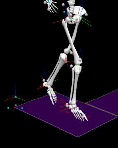
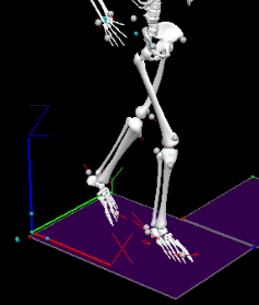
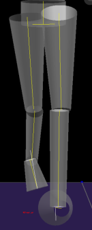
In some situations knee abduction/adduction angle may seem incorrect when visually evaluating video and/or skeleton data and comparing them to the signal in a graph. The angle may appear as abduction in the video/skeleton and plotted as adduction in graph. Please bear in mind that thigh segment's long axis is not aligned with femur. This can be best demonstrated on pictures (below). Last picture shows actual segment orientation as calculated and used in graph.
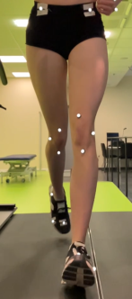
|
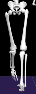
|
|
The position of the pelvis center of mass is calculated using the work of Tranberg (2010). The vertical position obtained during the static trial is then subtracted from the same position calculated during the running trial.
The angle of the foot with respect to the ground is computed in the sagittal plane. This is the angle between the longitudinal axis of the foot and the antero-posterior axis of the global coordinate system (virtual lab). The same angle is calculated during the static trial and subtracted from the value obtained during the running trial. The angle is equal to zero when both axes are parallel. A positive angle means the heel is below the toes when looking at the foot in the sagittal plane.
The angle of the thorax is given with respect to the global coordinate system (virtual lab).
The angles of the shoulders are given with respect to the pelvis in the biomechanical model.
The three-dimensional elbow angle is calculated from the SHOULDER, ELBOW and WRIST virtual markers. The angle is equal to 180° when these three markers are in one line (elbow fully extended).
The sagittal and frontal ankle trajectories are calculated using the position of the FAL marker in the sagittal and frontal plane, respectively.
The sagittal and frontal elbow trajectories are calculated using the position of the ELBOW marker in the sagittal and frontal plane, respectively.
The sagittal and frontal wrist trajectories are calculated using the position of the WRIST marker in the sagittal and frontal plane, respectively.
The time-series and trajectory patterns are normalized from foot strike (0%) to the next foot strike (100%). The right foot strike events are used for right patterns whereas the left foot strike events are used for left patterns. For unilateral patterns such as pelvis vertical position and trunk, shoulder and pelvis angles, the normalization was performed using right foot strike events. For the angle of the foot with respect to the global coordinate system, the normalization focuses on the first 25% of the contact phase. The contact phase is going from foot strike to take-off.
Examples: hip angle, knee angle, ankle angle
Example: pelvis angle
Note: the report shows the pelvis angle that follows the sign conventions for the right body side.
Angular velocities are calculated as the first derivatives of the angles after applying a 12 Hz lowpass filter. This means that they follow the same sign convention as the angles (e.g., while knee is flexing the velocity is positive, while knee is extending the velocity is negative).
The following table summarizes the list of variables calculated and exported from the processing engine.
| Parameter name | Definition |
| Spatio-temporal Parameters | |
| Running pace | Time per one kilometer (minutes/km). |
| Step length (left/right) | Distance between proximal end position of the contralateral foot at the previous contralateral heel strike to the proximal end position of the ipsilateral foot at the ipsilateral heel strike. |
| Step length (average) | Mean of left step length and right step length. |
| Stance time (left/right) | Time difference between consecutive ipsilateral foot strike and toe-off. |
| Contact time (Stance time) (average) | Mean of left stance time and right stance time. |
| Flight time | Time difference between consecutive contralateral toe-off and heel strike. |
| Stride width (average) | Medio-lateral distance between proximal end position of the foot at ipsilateral heel strike to the proximal end position of the foot at the next contralateral heel strike. |
| Steps per minute (Cadence) | 60 / step time. Step time is defines as time difference between consecutive contralateral foot strikes. |
| Flight-Contact time ratio | Flight time divided by contact time. |
| Discrete values | |
| Pelvis Height Range | Vertical difference of minimum and maximum position of pelvis center of mass. |
| Heel to Pelvis Distance at Foot strike (Left and Right) | Position of heel marker at foot strike subtracted from position of the pelvis origin onthe antero-posterior axis (x-component) (ie the reported distance is horizontal and in the running direction). |
| Peak foot pronation during stance (Left and Right) | Range from footstrike to peak pronation during stance. |
| Time to peak pronation during stance (Left and Right) | Time in percentage from foot strike to peak foot pronation during stance (% stance time). |
| Peak internal tibia rotation during stance | Peak internal tibia rotation (rotation of tibia relative to the foot) during stance. |
| Peak external tibia rotation during stance | Peak external tibia rotation (rotation of tibia relative to the foot) during stance. |
| Peak knee collapse | Range from footstrike to peak knee abduction during stance. |
| Peak knee rotation | Maximum internal knee rotation during stance. |
| Peak knee flexion | Maximum knee flexion during stance. |
| Time of peak knee flexion | Time in percentage from foot strike to peak knee flexion during stance (% stance time). |
| Peak hip collapse | Range from footstrike to peak hip adduction during stance. |
| Peak hip rotation | Maximum internal hip rotation during stance. |
| Peak hip extension | Range from footstrike to peak extension during the entire running cycle. |
| Hip flexion at foot strike | Hip flexion at footstrike event. |
| Peak pelvic drop | Range from footstrike to minimum pelvis obliquity during stance. |
| Curves (shown in report for complete running cycle) | |
| Vertical Position of the Pelvis | Position (z-component) of the origin of the pelvis subtracted by the position of the same point in the static trial. |
| Pelvis Tilt (Sagittal plane) | X-component of pelvis orientation relative to lab (Euler angle, see above). |
|
Pelvis obliquity (Frontal plane) |
Y-component of pelvis orientation relative to lab (Euler angle, see above). |
|
Pelvis Rotation (Transverse plane) |
Z-component of pelvis orientation relative to lab (Euler angle, see above). |
| Right/Left Hip Flexion-Extension | X-component of hip angle (Euler angle, thigh relative to pelvis). |
| Right/Left Hip Adduction/Abduction | Y-component of hip angle (Euler angle, thigh relative to pelvis). |
| Right/Left Knee Flexion-Extension | X-component of knee angle (Euler angle, shank relative to thigh). |
| Right/Left Knee Adduction/Abduction | Y-component of knee angle (Euler angle, shank relative to thigh). |
| Right/Left Knee Adduction/Abduction Angular Velocity | Y-component of knee angular velocity. |
| Right/Left Knee Internal/External Rotation | Z-component of knee angle (Euler angle, shank relative to thigh). |
| Right/Left Knee Internal/External Rotation Angular Velocity | Z-component of knee angular velocity. |
| Right/Left Tibia Rotation | Z-component of tibia rotation angle (Euler angle, shank relative to foot). |
| Right/Left Tibia Rotation Velocity | Z-component of tibia angular velocity. |
| Right/Left Ankle Flexion-Extension | X-component of ankle angle (Euler angle, virtual foot relative to shank) |
| Right/Left Ankle Pronation-Supination | Y-component of ankle angle (Euler angle, virtual foot relative to shank) |
| Right/Left Ankle Pronation-Supination Angular Velocity | Y-component of ankle angular velocity. |
| Shoulder Inclination wrt Pelvis (Frontal plane) | Y-component of trunk angle (Euler angle, thorax relative to pelvis). |
| Shoulder Rotation wrt Pelvis (Transverse plane) | Z-component of trunk angle (Euler angle, thorax relative to pelvis). |
| Thorax Inclination (Sagittal plane) | X-component of trunk angle (Euler angle, thorax relative to lab). |
| Right/Left Elbow Angle | 3D angle created by 3 landmarks (shoulder joint, elbow joint and wrist joint) |
| Curves (shown in report between Foot Strike and Midstance) | |
| Right/Left Foot Angle (Sagittal plane) | Angle between the longitudinal axis of the foot and the antero-posterior axis of the global coordinate system (virtual lab) |
| Trajectories | |
| Right/Left Ankle (Sagittal plane) during running cycle | Height is the z-component of the ankle marker. AP position is the x-component of the ankle marker, subtracted by the x-component of the pelvis position |
| Right/Left Ankle (Frontal plane) during running cycle | Height is the z-component of the ankle marker. ML position is the y-component of the ankle marker, subtracted by the y-component of the pelvis position |
| Right/Left Elbow (Sagittal plane) during running cycle | Height is the z-component of the elbow marker. AP position is the x-component of the elbow marker. Both components are subtracted by the pelvis position |
| Right/Left Elbow (Frontal plane) during running cycle | Height is the z-component of the elbow marker. ML position is the y-component of the elbow marker. Both components are subtracted by the pelvis position |
| Right/Left Wrist (Sagittal plane) during running cycle | Height is the z-component of the wrist marker. AP position is the x-component of the wrist marker. Both components are subtracted by the pelvis position |
| Right/Left Wrist (Frontal plane) during running cycle | Height is the z-component of the wrist marker. ML position is the y-component of the wrist marker. Both components are subtracted by the pelvis position |
Note: mean and SD values are based on all step cycles identified by the events defined above. Max and min values are the average max/min value from all step cycles.
Default reference data (also known as Normative data) that is displayed in the reports is based on the following two runners:
- Runner 1 (Male, 1.76 m , 60 kg, 3 speeds: 10-12-14 km/h)
- Runner 2 (Female, 1.65 m, 55 kg, 4 speeds: 12-14-16-18 km/h)