Rotation angle calculations in QTM
The following chapters contain information about rotation angle calculations in QTM for 6DOF data and skeleton data.
6DOF tracking output
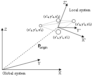
The 6DOF tracking function uses the rigid body definition to compute Porigin, the positional vector of the origin of the local coordinate system in the global coordinate system, and R, the rotation matrix which describes the rotation of the rigid body.
The rotation matrix (R) can then be used to transform a position Plocal (e.g. x'1, y'1, z'1) in the local coordinate system , which is translated and rotated, to a position Pglobal (e.g. x1, y1, z1) in the global coordinate system. The following equation is used to transform a position:
Pglobal= R ·Plocal + Porigin
If the 6DOF data refer to another coordinate system than the global coordinate the position and rotation is calculated in reference to that coordinate system instead. The coordinate system for rigid body data is then referred to the global coordinate system.
Calculation of rotation angles from the rotation matrix (Qualisys standard)
The rotation angles are calculated from the rotation matrix (R), by expressing it in the three rotation angles: roll (q), pitch (f) and yaw (y).
To begin with the rotations are described with individual rotation matrices: Rx, Ry and Rz. The rotations are around the X-, Y- respectively Z-axis and positive rotation is clockwise when looking in the direction of the axis.
The individual rotation matrix can be derived by drawing a figure, see example below. To get an individual rotation matrix express for example the new orientation x’ and y’ in the coordinates x, y and y and then make a matrix of the equations. The example below is of rotation around the Z-axis, where positive rotation of yaw (y) is clockwise when the Z-axis points inward.
The resulting three rotation matrices are then:
The rotation matrix (R) is then calculated by multiplying the three rotation matrices. The orders of the multiplications below means that roll is applied first, then pitch and finally yaw.
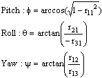
The following equations are then used to calculate the rotation angels from the rotation matrix:
The range of the pitch angle is -90° to 90°, because of the nature of the arcsin function. The range of the arcos function is 0° and 180°, but the range of roll and yaw can be expanded by looking respectively on the r23 and r12 elements in the rotation matrix (R). The roll and yaw will have the opposite sign compared to these elements, since cos(f) is always positive when f is within ±90°. This means that the range of roll and yaw are -180° to 180°.
A problem with the equations above is that when pitch is exactly ±90° then the other angles are undefined, because of the division by zero, i.e. singularity. The result of a pitch of exactly ±90° is that the Z-axis will be positioned at the position that the X-axis had before the rotation. Therefore yaw can be set to 0°, because every rotation of the Z-axis could have been made on the X-axis before pitching 90°. When yaw is 0° and pitch is ±90°, the rotation matrix can be simplified to:
From the matrix above the roll can be calculated in the range ±180°.
With the definitions above, roll, pitch and yaw are unambiguous and can describe any orientations of the rigid body. However, when the pitch (f) is close to ±90°, small changes in the orientation of the measured rigid body can result in large differences in the rotations because of the singularity at f=±90°.
Calculation of other rotation matrices
This chapter describes how other rotation matrices are calculated. The calculations are not described in the same detail for each matrix as with the Qualisys standard, but you should be able to calculate the exact rotation matrix from these descriptions.
If you use rotations around global axes the order of multiplication of the individual rotation matrices are reversed and if you use a left-hand system change the positive direction to counterclockwise, which means that the sign of the angle is swapped.
First there are two types of rotation matrices: those with three different rotation axes and those with the same rotation axis for the first and third rotation.
The first type is of the same type as the one used as Qualisys standard. This means that for this type the same individual rotation matrices (Rx, Ry and Rz) are used as for the Qualisys standard. The individual rotation matrices are then multiplied in different orders to get the different rotation matrix. When you have the rotation matrix the same kind of formulas but with other indexes and signs are used to get the rotational angles as for the Qualisys standard:
You have to look at the rotation matrix to see what indexes and signs that should be used. The singularity will always be at ±90° for the second rotation and at the singularity the third rotation is always set to 0°.
In the second type the third rotation is round the same axis as the first rotation. This means that one of the individual rotation matrices below is used as the last rotation, depending on which axis that is repeated.
The rotation matrix (R) is then calculated by multiplying two of the individual rotation matrices from the first type and then one of matrices above. In the example below the rotations are round the x, y and then x axis again.
The rotation angles can then be calculated according to the equations below. These equations are similar for other rotation matrices of this type, just the indexes and types are changed.
As for the first type of rotation matrices there will be a singularity for the second rotation angel, but now it is at 0° and 180°. The third rotation angle is then set to 0° and the following rotation matrix can be used to calculate the rotation. It will of course change for other matrices but the principle is the same.


