CAST marker set and model are based on paper by Cappozzo, A., Catani, F., Della Croce, U., Leardini, A. (1995). Position and orientation in space of bones during movement: anatomical frame definition and determination. Clinical Biomechanics, 10, 171-178.
CAST - Lower body session includes legs and pelvis and CAST - Full body session adds thorax, arms and head.
See marker guide at [your project]\Documentation (CAST_Marker_Set_Full_Body.pdf and CAST_Marker_Set_Lower_Body.pdf) for details of the marker placement.
AIM files are stored at [your project]\AIM models. Following files are used based on session selection:
If multisegment foot model is needed, it is necessary to go to [your project]\AIM models folder and manually replace above mentioned .qam file with its variant :
The marker set and model are derived from book by Richard Baker: Measuring Walking: A Handbook of Clinical Gait Analysis. London: Mac Keith Press; 2013.
See marker guide at [your project]\Documentation (CGM_Marker_Set_Full_Body.pdf and CGM_Marker_Set_Lower_Body.pdf) for details of the marker placement.
AIM files are stored at [your project]\AIM models. Following files are used based on session selection:
The marker set is derived from book by Richard Baker: Measuring Walking: A Handbook of Clinical Gait Analysis. London: Mac Keith Press; 2013.
Choose upper or lower body CGM session. Place markers according to the marker guide, noting the following important considerations below.
Choose how you would like to define the knee and ankle sagittal axis.
Presence of medial knee and medial ankle markers defines the frontal thigh and shank planes directly from medial and lateral knee and ankle markers. THI and TIB markers become tracking markers only and are not used in the definition of thigh and shank axis.
No medial markers means THI and TIB marker placement defines knee and ankle frontal plane. This requires THI and TIB markers to be precisely aligned; adjust the position of the THI marker so that it is lies in the plane that contains the hip and knee joint centres and the knee flexion/extension axis and the TIB marker should lie in the plane that contains the knee and ankle joint centres and the ankle flexion/extension axis (TIB marker).
If no medial knee (FME) and no ankle (TAM) markers are used, knee and ankle widths must be measured and entered in PAF.
If no medial knee and medial ankle markers are used then the marker size field must be entered correctly to calculate correct ankle and knee joint centres.
Both medial knee and ankle markers must be present or non-present in static trial. Situation when only one of them exist is not supported as it would lead to many possible combinations and inconsistent results if a marker is missing by mistake.
Choose to use a one segment foot model or multi-segment foot model using the PAF field "Multisegment foot" drop down menu.
If yes, you may choose to leave the leg length PAF field empty and leg length will be calculated as lateral ankle to ASIS distance, from the static trial.
If the participant has a crouched posture during the static trial, then leg length must be measured manually and entered in the relevant PAF field.
If leg length is measured and entered in the PAF field then this will be used instead of marker distances regardless.
If yes, then the PAF field "Normalise foot to static trial" option may be used to define the foot plane, which means calcaneus marker (FCC) height is not critical.
If the "Normalise foot to static trial" option is not selected, for example if the participant stands with some toe drop or is a toe walker, then the ankle sagittal angles will be determined directly by the calcaneus and 2nd metatarsal (FM2) markers. In this instance, care must be taken to ensure calcaneus and 2nd metatarsal markers are level with the long axis of the foot.
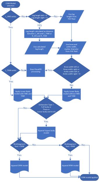
If L_FME and L_TAM markers exists in static trial, the lower body model (.mdh file) with shank and thigh defined from medial knee (FME) and medial ankle (TAM) is used.
If L_FME exists and L_TAM does not, a popup window appears to halt Visual3D process.
If L_FME does not exist in static trial, the PAF fields values are used:
If 'Leg length left' and 'Leg length right' are equal to 0, the leg length is calculated as the distance between IAS and TAM markers.
If all necessary PAF fields (Leg length left, Leg length right, Knee width left, Knee width right, Ankle width left, Ankle width right) are different than 0, the lower body model without medial markers is applied.
If one of the necessary PAF fields is equal to 0, a popup window appears to halt Visual3D process.
If session type is Full body, upper body model is appended to the existing model
If Multisegment foot PAF field value is OFM or RFM, the corresponding multisegment foot model is appended to the existing model.
For background about CGM2 markr set, please, refer to https://pycgm2.netlify.app/background/.
See marker guide at [your project]\Documentation (CGM2_Marker_Set_Full_Body.pdf and CGM2_Marker_Set_Lower_Body.pdf) for details of the marker placement.
Left Functional Knee trial and Right Functional Knee trial are needed only for CGM2.6. They have no function in earlier models.
Selection of CGM2 version is explained here.
AIM files are stored at [your project]\AIM models. We have prepared AIM file for all variants of model (see https://pycgm2.netlify.app/cgm/). By default we use CGM2.3. If you want to use other version it is necessary to rename corresponding .qam files to default name. Following files are available:
Default name - files used by the module:
Overwrite these models with new versions if required.
Additional files for other versions then CGM2.3:
Rename these files to the default name if you want to use other version. The names of the AIM models must match exactly so that QTM will select them automatically when you capture a file.
CGM1.0:
Static Full body: CGM10_Static_Full_Body.qam
Static Lower body: CGM10_Static_Lower_Body.qam
Gait Full body: CGM10_Dynamic_Full_Body.qam
Gait Lower body: CGM10_Dynamic_Lower_Body.qam
CGM1.1:
Static Full body: CGM11_Static_Full_Body.qam
Static Lower body: CGM11_Static_Lower_Body.qam
Gait Full body: CGM11_Dynamic_Full_Body.qam
Gait Lower body: CGM11_Dynamic_Lower_Body.qam
CGM2.1:
Static Full body: same as CGM11_Static_Full_Body.qam
Static Lower body: same as CGM11_Static_Lower_Body.qam
Gait Full body: same as CGM11_Dynamic_Full_Body.qam
Gait Lower body: same as CGM11_Dynamic_Lower_Body.qam
CGM2.2:
Static Full body: CGM22_Static_Full_Body.qam
Static Lower body: CGM22_Static_Lower_Body.qam
Gait Full body: CGM22_Dynamic_Full_Body.qam
Gait Lower body: CGM22_Dynamic_Lower_Body.qam
CGM2.3:
Static Full body: CGM23_Static_Full_Body.qam
Static Lower body: CGM23_Static_Lower_Body.qam
Gait Full body: CGM23_Dynamic_Full_Body.qam
Gait Lower body: CGM23_Dynamic_Lower_Body.qam
CGM2.4:
Static Full body: CGM24_Static_Full_Body.qam
Static Lower body: CGM24_Static_Lower_Body.qam
Gait Full body: CGM24_Dynamic_Full_Body.qam
Gait Lower body: CGM24_Dynamic_Lower_Body.qam
CGM2.5:
Static Full body: CGM25_Static_Full_Body.qam
Static Lower body: CGM25_Static_Lower_Body.qam
Gait Full body: CGM25_Dynamic_Full_Body.qam
Gait Lower body: CGM25_Dynamic_Lower_Body.qam
CGM2.6:
Static Full body: same as CGM25_Static_Full_Body.qam
Static Lower body: same as CGM25_Static_Lower_Body.qam
Gait Full body: same as CGM25_Dynamic_Full_Body.qam
Gait Lower body: same as CGM25_Dynamic_Lower_Body.qam
See marker guide at [your project]\Documentation\Gait_Overlay_Marker_Set.pdf for details of the marker placement.
This session works just like normal gait session but requires four markers on foot and force plate data. Word report or PDF report are available showing load analysis and force video overlay pictures at initial contact of force plate (ON), loading response (LR), midstance (MS), terminal stance (TS) and last contact on forceplate (OFF) events with force vector overlay. Video cameras are optional, screenshots are shown in Word report if at least one video exists. See Word report chapter for addition info. Only 'Multiple forceplates' and 'Single forceplate' event modes work for Gait Overlay session.
AIM files are stored at [your project]\AIM models. Following files are used based on session selection:
IOR_Left_Foot.qam
IOR_Right_Foot.qam
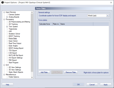
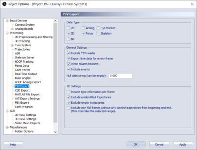
Note that specific export settings are required for force vector to be overlayed correctly. In project options > Processing > Force Data set 'Coordinate system for force/COP display and export' to World (Lab). In TSV Export check Force data type, 3D data type and all check boxes on General Settings.
IOR marker set and model are based on paper by Leardini, A., Biagi, F., Merlo, A., Belvedere, C., & Benedetti, M.G. (2011). Multi-segment trunk kinematics during locomotion and elementary exercises. Clinical Biomechanics, 26, 562-571. doi: 10.1016/j.clinbiomech.2011.01.015
IOR - Lower body session includes legs and pelvis and IOR - Full body session adds thorax, arms and head.
See marker guide at [your project]\Documentation (IOR_Marker_Set_Full_Body.pdf and IOR_Marker_Set_Lower_Body.pdf) for details of the marker placement.
AIM files are stored at [your project]\AIM models. Following files are used based on session selection:
If multisegment foot model is needed, it is necessary to go to [your project]\AIM models folder and manually replace above mentioned .qam file with its variant:
Requirements for Theia3D are well described in Theia3D documentation. Here is an extract from it:
Theia3D provides 3D pose estimates that are robust to changes in attire. General recommendations for subject attire include:
Body-fitting clothing. Each limb should be discernible from the rest of the body.
Clothing should provide rich visual features, such as visible creasing, shadows, or other textures.
Lighting is often more important than attire color, as it impacts the visual richness of the attire. Under adequate lighting conditions black attire is acceptable, but lighter colors generally provide more visual features.
Static overlay session requires only force plate data from two force plates. Patient has to stand with one foot on each force plate.
Optionally it is possible to add IOR spine and pelvis markers as published by Leardini, A., Biagi, F., Merlo, A., Belvedere, C., & Benedetti, M.G. (2011). Multi-segment trunk kinematics during locomotion and elementary exercises. Clinical Biomechanics, 26, 562-571. doi: 10.1016/j.clinbiomech.2011.01.015.
See marker guide at [your project]\Documentation\IOR_Spine_Marker_Set.pdf for details of the marker placement.
Word report settings are described here.
Stabilometry session allows to collect 30 second static measurement to evaluate stabilometry parameters.
Ideally patient will stand with both feet on one force plate, optionally with each foot on separate force plate.
No markers are needed.
Word report or PDF report are generated showing statokinesiogram and additional stabilometry parameters.
By default pictures for the first 4 videos are shown. To show other videos (if there is more then 4 videos) or to change the order of videos in Word report, go to [your project]\Templates\settings.php and change $overlay_camera_serial_numbers to list of serial numbers of videos you want to be shown in the report. Pictures will be shown in the same order as specified in $overlay_camera_serial_numbers.
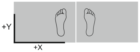
It is important that L frame orientation is is as shown in this picture for anterior-posterior and medial-lateral components of COP traces and parameters to be correct.