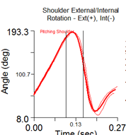
All Plots show mean (thick line) and all individual pitches (thin lines). The plots are aligned to begin and end at the cylinder start and end events. Vertical lines on the plots show the pitching events that occur in that cylinder (Setup, Max opp knee height, Footstrike, Max shoulder Ext Rot, and ball release). For example, the plot below is for Cylinder 7 which starts at footstrike and ends at 10ms after ball release. The two vertical lines in the plot represent max shoulder external rotation and ball release.
All five rear mound markers are placed symmetrically on the edges of the pitcher’s rubber.
The purpose of the two bottom markers is to estimate the slope of the mound. The slope is approximated by a line from the midpoint of the front rubber markers to the midpoint of the bottom markers. The bottom markers should be placed symmetrically at the bottom end of the mound, adjacent to the area where the front foot of the pitcher makes contact with the mound, thereby making sure not to impede the pitcher.
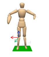
The lab coordinate system is typically placed with the x-axis (long axis of L-frame) on the rubber and the y-axis aligned with the target line but other L-frame orientations are supported as well.
The L-frame should be level.
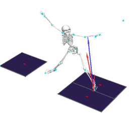
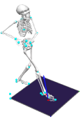
Optionally force plates can be used. Following picture shows default force plate layout. Module will work if only plant leg GRF is available but some kinetics parameter related to combined force will be missing.
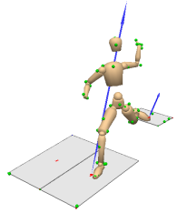
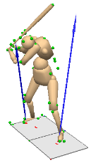
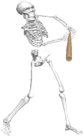
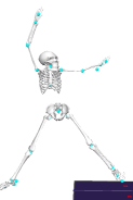
| Baseball pitching | Baseball hitting | Softball pitching |
|
|
|
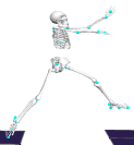
Each body segment is represented by a rigid segment.
|
|
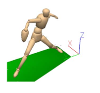
General convention: x-axis points to the right side y-axis point to the front z-axis points up The example to the left shows the coordinate system of the left shank.
|
|
Event |
Image |
Can be set in QTM |
Definition |
|
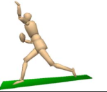
Setup |
|
Yes |
Vertical speed of opposite heel marker exceeds 0.02 m/s, offset by -1 frame. |
|
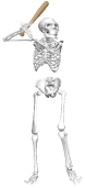
Max Leg Lift |
|
No |
The opposite knee reaches its maximum height. |
|
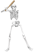
Footstrike |
|
Yes |
If not set manually and if not identified from force data, the first of the following two events is used: (1) Toe marker reaches the same height (relative to the surface of the mound) as in the static trial. (2) Heel marker reaches the same height as at the start of the capture (Setup event), plus 5 mm.
|
| Block |
|
Yes | Optional. Block happens after footplant and is derived from knee flexion/extension. After the footplant, knee tends to extend. |
|
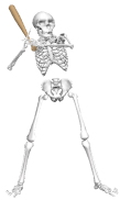
Release |
|
Yes |
If not defined manually, maximum value of pitching hand angular velocity is used. Note: If this event is not present, data will not be graphed in the report. |
During the arm-cocking phase, which ends at maximum shoulder external rotation, the throwing arm produces maximum anterior shoulder force, horizontal adduction torque, internal rotation torque, and elbow varus torque. During the arm acceleration phase (between MER and BR), maximum elbow flexion torque is achieved. Immediately after BR, when the arm begins to decelerate, maximum proximal shoulder force and proximal elbow force occur.
|
Event |
Image |
Can be set in QTM |
Definition |
| Setup |

|
Yes |
Vertical speed of opposite heel marker exceeds 0.1 m/s, offset by -1 frame. |
|
Lead_Foot_Off |
|
Yes |
No Force data: Toe marker moves 0.07 m vertically above ground shifted by -0.04 s backward. Force data exists: First GRF of lead foot crossing of 10 N on descent. |
|
Lead_Foot_Down |
|
Yes |
No force data: Global minimum of Z component of lead toe velocity shifted by 0.1 s forward Force data exists: First GRF of lead foot crossing of 10 N on ascent. |
| Lead_Foot_Flat |
|
Yes | If event exists, time between Lead Foot Down and Lead Foot Flat is calculated. |
|
Contact |
|
Yes |
If not defined manually, maximum bat angular velocity is used. Note: If this event is not present, data will not be graphed in the report. |
|
Event |
Image |
Can be set in QTM |
Definition |
| Setup |
|
Yes | Instance when glove hand starts moving down. |
| MaxKneeHeight |
|
No | Maximum vertical position of lead leg |
| Back_Leg_Footoff |
|
Yes |
No Force data: Instance when back foot maximum between Max Knee Height and Lead Leg Footstrike Force data exists: Last OFF event of Back Leg between Setup and Lead Leg Footstrike |
| Backswing Top |
|
No | Maximum height of throwing hand vertical position |
| Lead_Leg_Footstrike |
|
Yes |
No Force data: Instance when lead foot vertical velocity goes to zero and Max Knee Height. Force data exists: First ON event of lead foot |
| Release |
|
Yes |
Maximum of magnitude angular velocity of throwing hand |
Visual 3D creates joints where any two segments in proximity (the distal end of one segment and the proximal end of another segment within the radius of the segment ends) to be "linked" and references a Joint between them. The Joint does not constrain the segments, but is rather a bookkeeping tool that keeps track of which segments are assumed to have an equal and opposite Joint Reaction Force acting between their endpoints and an equal and opposite Joint Moments acting on the adjacent segments.
Joint_Radius_Ratio: If the segment ends are separated by more then 1.1 times the larger segment end radius, then no joint is formed. Visual3D checks to see if the distal end of the neighbour is close enough to the proximal end of the segment. Default is 1.1 for all models except Driveline where that is set to 1.4.
Shoulder joint position is calculated as Marker_Radius+0.17*Distance(LSHO,RSHO). Calculation is based on upper extremity model developed by Dr. George Rab, Kyria Petuskey, and Anita Bagley from Shriners Hospital for Children, Northern California, see their paper "A Method for Determination of Upper Extremity Kinematics" Gait & Posture 15 (2002) 113-119.
Rather than flipping the trunk where the proximal end of the segment is the pelvis/hip and the distal is the shoulders, we have created clavicle segments attached to the thorax segment. The clavicles are created with the proximal segment joint as the origin of the trunk and the distal segment joint as the shoulder marker. Right and left are separate. The segment proximal and distal segments radius are 0.25*distance(RIGHT_SHOULDER,C7). Note some models may vary depending on marker names and if C7 exists in that model. Variations may use Chest marker. This is a kinetic segment where the segment is modelled as a cylinder with a very small mass of 0.1 Kg.
With shoulder joint created consistently in all the models, we move to Shoulder Torque and Shoulder Angular Velocity at ZYZ order to match the shoulder angle order.
|
Segment |
Definition |
Sign convention |
Programming notes |
|
Pitching Shoulder1 |
Pitching Upper Arm wrt Thorax |
Horz Add +, Horz Abd – Ext Rot +, Int Rot - |
Order: ZYZ Negate L: TFF Negate R: FTT |
|
Glove Shoulder1 |
Glove Upper Arm wrt Thorax |
Horz Add +, Horz Abd – Ext Rot +, Int Rot - |
Order: ZYZ Negate L: TFF Negate R: FTT |
|
Pitching Shoulder_XYZ12 |
Pitching Upper Arm wrt Thorax |
Abd +, Add - |
Order: XYZ Negate L: FFF Negate R: FTT |
|
Glove Shoulder_XYZ12 |
Glove Upper Arm wrt Thorax |
Abd +, Add - |
Order: XYZ Negate L: TFF Negate R: FFF |
|
Pitching Elbow |
Pitching Upper Arm wrt Lower Arm |
Flex +, Ext - |
Order: XYZ Negate L: FFF Negate R: FTT |
|
Glove Elbow |
Glove Upper Arm wrt Lower Arm |
Flex +, Ext- |
Order: XYZ Negate L: FFF Negate R: FTT |
|
Pitching Hand |
Pitching Lower Arm wrt Hand |
Flex +, Ulnar dev +, Pro + |
Order: XYZ Negate L: FFT Negate R: FTF |
|
Lead Hip |
Lead Thigh wrt Pelvis |
Flex +, Add +, Int Rot + |
Order: XYZ Negate L: FTT Negate R: FFF |
|
Lead Knee |
Lead Shank wrt Lead Thigh |
Flex +, Var +, Int Rot + |
Order: XYZ Negate L: TTT Negate R: TFF |
|
Lead Ankle |
Lead Virtual Foot wrt Lead Shank |
Dorsi +, Inv +, Int Rot + |
Order: XYZ Negate L: FTT Negate R: FFF |
|
Back Hip |
Back Thigh wrt Pelvis |
Flex +, Add +, Int Rot + |
Order: XYZ Negate L: FTT Negate R: FFF |
|
Back Knee |
Back Shank wrt Back Thigh |
Flex +, Var +, Int Rot + |
Order: XYZ Negate L: TTT Negate R: TFF |
|
Back Ankle |
Back Virtual Foot wrt Back Shank |
Dorsi +, Inv +, Int Rot + |
Order: XYZ Negate L: FTT Negate R: FFF |
| Back Foot | Back_Foot_wrt_Lab | Out +, In - |
Order: XYZ Negate L: FFT Negate R: FFF |
|
Head |
Head wrt Virtual Lab |
Flex +, Ext - |
Order: XYZ Negate L: TFF Negate R: TFT |
|
Trunk |
Thorax wrt Virtual Lab |
Fwd Flex +, Lat Flex + contralat |
Order: XYZ Negate L: TFF Negate R: TTT |
|
Pelvis |
Pelvis wrt Virtual Lab |
Fwd +, Obliq + Up ipsi |
Order: XYZ Negate L: TFF Negate R: TTT |
|
Trunk wrt Pelvis |
Thorax wrt Pelvis |
Fwd Flex + |
Order: XYZ Negate L: TFF Negate R: TTT |
1) In the current model, shoulders are regarded as part of the thorax, so contributions from trunk hyperextension and scapulothoracic movement will not be included in the reported angle for the most part (Miyashita, Kobayashi, Koshida, & Urabe, 2010).
2) X and Z components often do not yields reasonable values due to gimbal lock issue. That is why they are not used in report. Use with caution when using for your own interpretation.
|
Segment |
Definition |
Sign convention |
Programming notes |
|
Pitching Shoulder Ang Vel2 |
Pitching Upper Arm wrt Thorax; resolution coordinate system: humerus |
Horz Add + |
Order: ZYZ Negate L: TFF Negate R: FFT |
|
Glove Shoulder Ang Vel2 |
Glove Upper Arm wrt Thorax; resolution coordinate system: humerus |
Horz Add + |
Order: ZYZ Negate L: TFF Negate R: FTT |
|
Arm Ang Vel |
Humerus wrt Virtual Lab, resolution coordinate system: humerus |
Ext Rot - |
Order: XYZ Negate L: TFT Negate R: FFF |
|
Pitching Elbow Ang Vel |
Pitching Upper Arm wrt Lower Arm, resolution coordinate system: forearm |
Flex + |
Order: XYZ Negate L: FFF Negate R: FFF |
|
Pitching Hand Ang Vel |
Pitching Hand wrt Virtual Lab, resolution coordinate system: hand |
Flex + |
Order: XYZ Negate L: FFT Negate R: FTF |
|
Lead Hip Ang Vel |
Lead Thigh wrt Pelvis, resolution coordinate system: thigh |
Flex + |
Order: XYZ Negate L: FTT Negate R: FFF |
|
Lead Knee Ang Vel |
Lead Shank wrt Lead Thigh, resolution coordinate system: shank |
Flex + |
Order: XYZ Negate L: TTT Negate R: TFF |
|
Lead Ankle Ang Vel |
Lead Virtual Foot wrt Lead Shank, resolution coordinate system: virtual foot |
Dorsi + |
Order: XYZ Negate L: FTT Negate R: FFF |
|
Back Hip Ang Vel |
Back Thigh wrt Pelvis, resolution coordinate system: thigh |
Flex + |
Order: XYZ Negate L: FTT Negate R: FFF |
|
Back Knee Ang Vel |
Back Shank wrt Back Thigh, resolution coordinate system: thigh |
Flex + |
Order: XYZ Negate L: TTT Negate R: TFF |
|
Back Ankle Ang Vel |
Back Virtual Foot wrt Back Shank, resolution coordinate system: virtual foot |
Dorsi + |
Order: XYZ Negate L: FTT Negate R: FFF |
|
Trunk Ang Vel |
Thorax wrt Virtual Lab, resolution coordinate system: thorax |
Fwd Flex + |
Order: XYZ Negate L: TFT Negate R: TTF |
|
Head Ang Vel |
Head wrt Virtual Lab, resolution coordinate system: head |
Flex + |
Order: XYZ Negate L: TFT Negate R: TFF |
|
Pelvis Ang Vel |
Pelvis wrt Virtual Lab, resolution coordinate system: pelvis |
Fwd + |
Order: XYZ Negate L: TFT Negate R: TTF |
2 Shoulder rotation velocity is not calculated as the first derivative of the joint angle components but by a vector that describes the angular velocity of one segment (upper arm) relative to another (thorax), using the upper arm coordinate system as reference frame. Both approaches were found to produce very similar results in case of shoulder internal rotation velocity. For details on the algorithm used see http://www.cmotion.com/v3dwiki/index.php?title=Joint_Velocity
|
Segment |
Definition |
Sign convention |
Programming notes |
|
Trunk |
Magnitude of velocity of Trunk COG |
|
|
|
Pelvis |
Magnitude of velocity of Pelvis COG |
|
|
|
Back Foot |
Back Foot COG position – Back Foot COG wrt Virtual Lab, resolution coordinate system: virtual lab |
Toward home plate |
Order: XYZ Negate: FFF |
|
Lead Knee |
Lead dynamic knee joint center wrt virtual lab |
Toward home plate |
|
|
Back Knee |
Back dynamic knee joint center wrt virtual lab |
Toward home plate |
|
|
Trunk Velocity |
Trunk COG velocity - Thorax COG wrt Virtual Lab, resolution coordinate system: virtual lab |
Toward home plate |
Order: XYZ Negate: FFF |
|
Pelvis Velocity |
Pelvis COG velocity - Pelvis COG wrt Virtual Lab, resolution coordinate system: virtual lab |
Toward home plate |
Order: XYZ Negate: FFF |
|
Segment |
Definition |
Sign convention |
Programming notes |
| Lead Shoulder Moment |
Shoulder Torque - Normalized to either Mass or BW or BW*BH or MASS*BH Internal moments |
Add+, Abd +, Horz Abd +, Horz Abb -, Int Rot +, Ext Rot - |
Negate L: FTT Negate R: TFF |
| Lead Elbow Moment |
Elbow Torque - Normalized to either Mass or BW or BW*BH or MASS*BH Internal moments |
Ext +, Flex- Var+, Val- |
Negate L: TTT Negate R: TFF |
| Lead (Plant) Leg GRF | Lead_Leg_GRF |
Normalized to BW Negate L: TFF Negate R: FFF |
|
| Trail (Back) Leg GRF | Back_Leg_GRF |
Normalized to BW Negate L: TFF Negate R: FFF |